Dreamcast Dev Bios (Part 2)


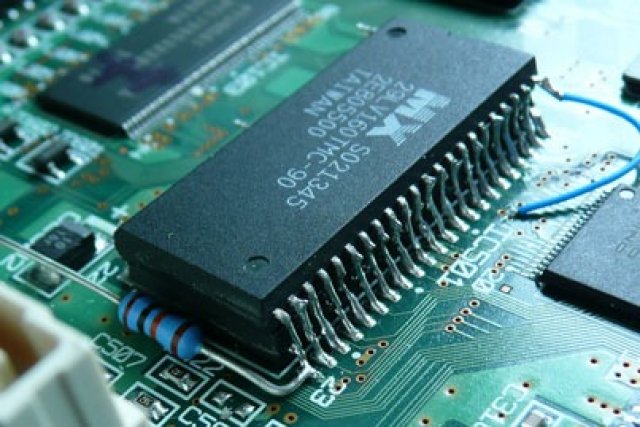
It could be that the legs on the new flash chip have been bent too much, and you need to pull them out a bit so that they are level with the old chip legs, then try the same technique of dragging the solder from the old leg to the new leg.
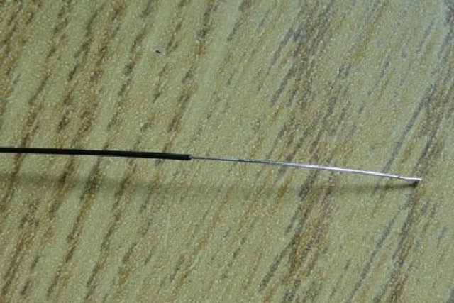
If that doesn't work, then we can add a piece of wire, this is Kynar wire, I've stripped a length of exposing a couple of centimetres of bare wire.

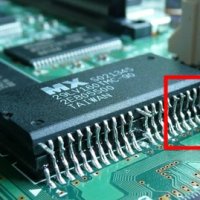
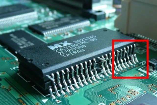
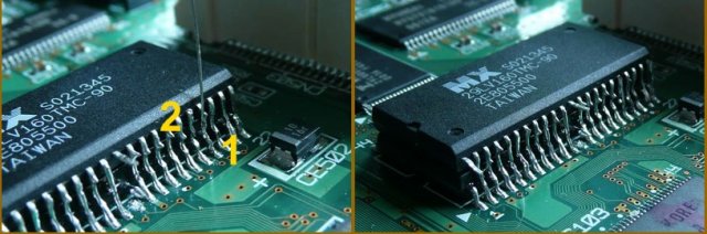
Hold the wire in place, heat up the solder on the old chip leg (Number 1 below), then heat up the solder that you had previously dragged up onto the new chips legs (Number 2), then trim the wire. Repeat this on all the legs.

Now, you can test your soldering again. Check each leg with a continuity tester and make sure that it confirms that the old and new leg are soldered together. If you think you've put too much solder on a leg and joined to adjacent legs, then you could test this also (remember that legs 32 and 33 are already linked up)
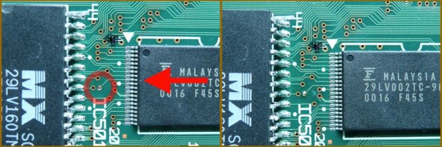

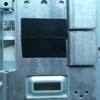
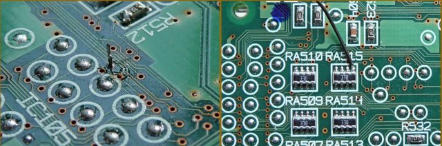
Lets start with the most awkward wire to solder now. The leg of the flash chip needs to be linked to pin 9 of the adjacent chip just behind it (assuming VA1 motherboard, on the VA0 motherboard it's leg 7). Look how small those legs are! You should be able to see that the leg is linked up to a small hole on the motherboard, I gently scraped the coating from that hole (you can see that in the first photo above), and then melted a small bit of solder onto the point.

You can see the short piece of Kynar wire that I've used to link leg 44 to the contact point.

Alternatively, if you're using Kynar wire, you can strip it and push it through the whole and solder it onto the other side. If you still don't fancy that, it's linked up to a leg on RA515 which is on the bottom of the motherboard (these photos are from a VA1 motherboard, it may look different on the VA0)

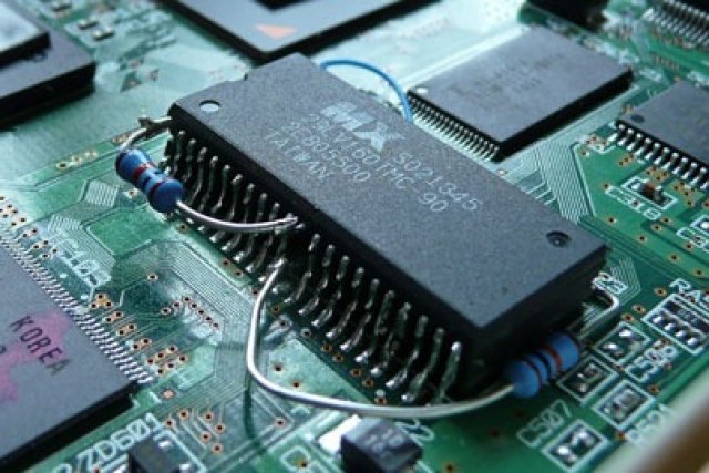

Now grab your 10k resistors, you can see how I've bent and soldered the first one to the joined up legs 23, and the other end of that goes to the lifted leg 12 of the existing BIOS chip. The second resistor was cut and bent to fit between legs 1 and 12 of the new Flash chip.

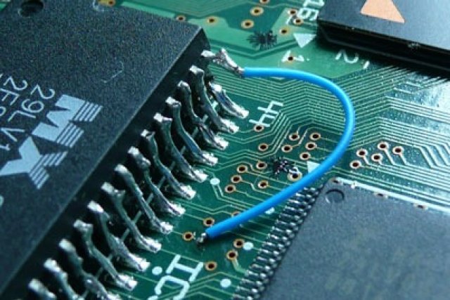
Once the resistors are in place, solder a final wire inbetween leg 1 of the new chip (there's already a resistor soldered to it remember), to the linked up legs 23 of both legs (opposite corner of chips, also has a resistor coming off of it). That's the green wire in the photo above.
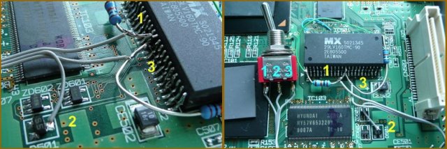

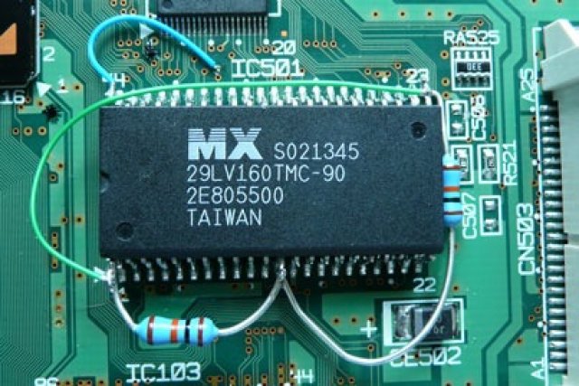
Now it's time to solder the switch in place. I hope the numbered photos above explain what to solder to each leg etc. Middle contact of the switch to the single point of D501 on the motherboard, either side of the switch contacts to the resistors near where they link up to legs 12 of the chips. The switch is used to select which BIOS is loaded when you switch the console on, either the existing one or Link83s modified one.