Developer's notes for the Atari TT030

THE TT030 COMPANION: DEVELOPER'S NOTES FOR THE ATARI TT030
This document contains a preliminary version of the information a developer should have concerning the TT030, in addition to the existing ST and STe documentation.
OVERVIEW
A TT030 is an ST running on a 32Hz 68030, with the following changes (in broad terms):
- Additional RAM expandability. with fast. nybble-mode RAM.
- SCSI DMA for SCSI hard disks and other devices.
- DMA digital stereo sound (as found in the STe).
- Addition of a 68882 floating-point coprocessor.
- Additional video modes (details later).
- Addition of an 8530 SCC (serial communications controller). giving a Localtalk connector (with DMA) and one extra serial port. or two extra serial ports.
- Internal speaker.
All this new hardware required some changes to the internal software. particularly in the BIOS. GEMDOS changed a little. Changes to AES and VDI were made as required to support the new resolutions, as well as changes to the desktop to allow cache control.
The most important thing to remember about the TT is that it is ST compatible and therefore GEM compatible. As a result. for the majority of applications, ALL of the normal things that applications need to do are done trough GEM. just like an ST. The documentation that you have on the AES, VDI, GEMDOS, XBIOS, and BIOS are still valid and are correct for the TT. The eXtensions to these things for hardware specific areas are outlined in the following.
THE NEW HARDWARE
THE 68030
The 68030 has two caches: an instruction cache and a data cache. Details on them are available in the 68030 documentation. TOS boots with the cache off. but there is an option on the Desktop to enable it (just like the Blitter switch on a Mega). Programs normally do not notice the presence of the cache (except that they run faster!), but programs which modify memory, then execute it (e.g. self-modifying code) will need examination, and any program which uses DMA directly Cas opposed to making the BIOS or XBIOS calls) needs to invalidate the caches after the DMA operation completes, before accessing the memory which may have been changed by the DMA.
The 68030 has a full 32-bit address bus, not the 24-bit bus of the 68000. Programs using the high 8 bits of addresses for any reason (e.g. a type field for a pointer) will not run on the TT030.
Naturally, the 16MHz 68030 with a 32-bit data bus runs faster than the 8MHz 68000 with a 16- bit data bus. Programs which rely on instruction timing will not run correctly.
Those of you that are doing assembly language programming or debugging can get more detailed information from the 68030 user's manual by Motorola: MC68030UM/AD REV 1. "Enhanced 32-Bit Microprocessor User's Manual, Second Edition". The 68030 will run user- mode-only 68000 programs, with one slight hitch: the move from SR instruction is now privileged. Some compilers, notably Alcyon C 4.14, use this instruction. The BIOS has a handler for the privilege violation exception, which checks for this instruction: it replaces the instruction with a move from CCR and tries running it again. This is sufficient for most programs.
Authors of programs which perform supervisory operations (e.g. respond to traps) need to know about one other. crucial change: the exception stack frame format is changed. There is an extra word on the stack after the return SR and PC. That means that if a trap was made from supervisor mode, the arguments the caller pushed are one word farther away from the top of the stack than they are on a 68000. This is the case for all680x0 processors except 68000. There is a new system variable, _longframe, at $59e: if-this word is nonzero, you are running on a CPU which uses the long stack frame format. (See the Cookie Jar documentation for the way to tell what CPU you're running on.)
MEMORY
There are three kinds of memory in a TT030.
- ST RAM is dual-purpose RAM, shared between the CPU and all the ST devices (video, ACSI DMA, OMA sound). The machine comes with 2MB of this kind of RAM, and is expandable with another 2MB of this RAM.
- TT RAM is single-purpose RAM: it is not shared among the ST-compatible devices. Accesses to it are faster because the CPU never has to wait for its tum. It's also faster because it is "nybble mode" RAM, meaning the 68030 can use "burst fill" accesses to rapidly fill its caches. It is not visible to ACSI DMA, DMA sound, or video. It is visible to the CPU and to SCSI DMA. The TT030 has room for one TT RAM board containing 4MB (or 16MB with 4Meg parts).
- VME RAM is memory which exists on the VME bus. Because it goes through the VME bus, and because the VME bus data path is only 16 bits wide, it is about the same speed as RAM in ST. It is.visible only to the CPU. (It's not visible to SCSI DMA, because that requires a 32-bit data path.)
SCSI DMA
A SCSI (Small Computer System Interface) bus is available on the TT030. What this means to developers and purchasers is that almost any SCSI hard disk drive can be connected to a TT030 with a minimum of trouble. The Atari hard-disk utilities can recognize, format. partition, and install (make bootable) almost any SCSI drive. (SCSI. though a standard, is not always implemented the same way by all vendors. and it is possible that some nominally SCSI drives won't work with the TT030.)
There are other types of SCSI devices than hard disks. Streaming tapes, 9-track tapes, and network node connection devices are available, along with other types of devices. These will connect just fine to the TT030, but the vendor, a value-added reseller, or the user will have to come up with the drivers for them.
There is one internal SCSI connection in the TT030; it's a 50-pin connector for a ribbon cable, and there's room for a 3-1/2" drive inside. In addition. there is a 25-pin external SCSI connector which is compatible with the other 25-pin SCSI connectors in the industry (read "Mac"). You should be able to buy such a hard drive "off the shelf' and plug it right in to a TT030.
DMA SOUND, INTERNAL SPEAKER
The DMA sound features of the TT030 are just like those of the STe series. The hardware registers are at the same addresses and have the same functions. The audio signal from the DMA sound system and the ST-compatible sound generator are (optionally) mixed in the volume/tone controller and sent to the internal speaker and to the left/right RCA jacks on the back of the machine. A switch is provided to disable the internal speaker: it's bit 6 in Port A of the PSG's general-purpose output registers.
68882
The TT030 comes with a Motorola 68882 floating-point coprocessor. This can be used by programs to do floating-point computations very quickly. No provision is made for sharing this. however, so it should not be used by accessories or from interrupts. (Multitasking systems will have to save and restore the state of the 68882 just like they save and restore the state of the CPU registers when changing from one process to another.)
VIDEO
The TT030 supports all three of the ST video modes, plus three new ones. The modes are as follows:
STLOW STMEDIUM ST HIGH TTLOW TTMEDIUM TTHIGH
 320x200 16 colors
 640x200 4 colors
 640x400 2 colors (not just black & white)
 320x480 256 colors
 640x480 16 colors
1280x960 black and white
All the ST resolutions, and the two color TT resolutions, are displayable on the same kind of monitor. TT HIGH resolution 0280x96Q) is available only on special monitors; appropriate monitors or a list of vendors and models which are compatible will be available from Atari.
The color palette is like the STe: four bits each for red, green, and blue, giving a total of 4096 colors. In the ST-compatible color look-up table (CLUT) at $FFFF8240 (same as on the ST and STe), the high bit of each nybble is the low bit of the corresponding gun value for red, green, and blue. In addition, at a new address ($FFFF8400), there is a 256-entry CLUT with the bits in the more natural order. In the 16-color modes (and the 4-color mode), the 256-color CLUT is divided into 16 "banks," and only one of these "banks" is active at any time. It is the active bank which is visible in the 16-entry ST-compatible CLUT. Changing banks requires only one write to the video chip, so you can use the bank system to change all l6 colors at once. There are new XBIOS calls for accessing the color tables and shifter mode registers.
ST HIGH resolution is now called "duochrome" on the TT030 because you can display any two colors, not just black and white. The two colors which are displayed are the last two in the 256-entry CLUT. In addition, a bit is used to invert the display, just like the ST's high- resolution mode. The bit in question is bit 1 (not bit Q) of the first ent~y in either CLUT.
The existence of the new video modes will reveal the lazy programming practices of developers who make assumptions about the screen, like its resolution, the number of colors available, and the size of the screen image in memory. It has always been possible to use the VDI enquire functions, or even examine the Line-A variable space, to determine the characteristics of the display. Even writing "resolution-independent" code which calls Getrez() is not good enough, since Getrez() will return values for the new modes which were impossible (and therefore unanticipated) on an ST. Use the VDI to get the information that you need.
In general. only the most careful programmers have avoided all assumptions in this area. Programs which use AES/VDI exclusively will often work in the new modes, allowing their users to take advantage of the larger screen space, colors, etc. Other programs will need to be modified, or will be restricted to running in the ST-compatible modes.
SCC AND OTHER SERIAL PORTS
The TT030 has three new serial ports. Two of them come from the 8530 SCC (Serial communications Controller): these have all the modem control signals. One of those shares the hardware with the Localtalk-compatible LAN (local-area network) connector: you can use either LAN or that serial port, but not both at the same time.
The other new port comes from the new 68901 MFP. It works just like the ST-compatible port, except that it only has transmit, receive and ground signals: there are no modem control signals on that port.
The BIOS has support for all of these ports, including XON/XOFF or RTS/CTS flow control. and provisions for compatibility with existing programs. See the documentation for the Bconmap call for more. (Naturally, the new 68901 port doesn't support RTS/CTS, since these signals are not available.)
**********************************************************************
TOS CHANGES
The TOS version number for the first release of TT TOS is TOS 3.0. Until that ROM is finalized, all TT ROMs will have TOS version number 3.0, and finer distinctions will be made with the date code in the OS header.
**********************************************************************
GEMDOS CHANGES
TWO KINDS OF RAM
This section will discuss the concept of "alternative RAM" in general first, and gets to the specifics as the relate to the TT030 later.
In the TT030 and other ST-like machines planned for the future, there are two general kinds of RAM: there is STRAM, which is ST-compatible, and there is "alternative RAM," which is not. Exactly how it is not varies by machine and type of RAM. Primarily, the video chip can only display screen data from ST RAM, and the DMA sound chip can only play data stored in STRAM. Secondarily, other chips which access memory, like ACSI DMA (forST hard disks and other devices) and SCSI DMA (for SCSI devices), may not be able to get at alternative memory directly. This affects most programs not at all, since they use BIOS and GEMDOS calls to accomplish this kind of transfer, and the device driver is responsible for getting the data from here to there transparently, no matter where "here" and "there" are.
The "rules for eligibility" for a program running in alternate RAM are:
- It must not try to set the screen base address in alternative RAM, or play DMA sound from there.
- It must not try to make a device driver do DMA from or to there, unless the device driver knows about the differences between ST RAM and alternative RAM.
- It must not try to do DMA itself from or to there (only specialized device drivers do this).
The second point is a bit sticky: it refers to the fact that existing DMA device drivers don't know about the restrictions on alternative RAM.
Since programs written before there was any concept of alternative RAM don't know if they break the rules or not, you, the user, must inform GEMDOS as to whether a program is eligible to use alternative RAM. or must use STRAM. As a finer distinction, you can select the eligibility for program loading and Malloc() calls separately. A program which Malloc's a screen buffer might still be eligible to load into alternative RAM, but its Malloc() calls must be satisfied from ST·RAM.
THE SPECIFICS ON TWO KINDS OF RAM
As of Rainbow TOS, one of the reserved longwords in the header of executable files CPRG, TTP. TOS) acquired a meaning: the bits there control the way GEMDOS treats that program. (The least-significant bit of that longword (bit 0), when set, means GEMDOS need not clear all of RAM when loading that program. only the program's declared BSS. This makes programs load faster.)
The next two bits have been assigned meanings relating to alternative RAM. Bit 1. when clear, means that the program must be loaded into ST RAM; bit 2. when clear, means that Malloc calls by that program must be satisfied using STRAM.
When one of these bits !s set, the corresponding operation (program load, Malloc call) may be satisfied from "alternative" RAM. In general, alternative is considered preferable to STRAM. If a program doesn't break any of the rules for eligibility in alternative RAM, it is desirable to set those bits in its header.
If TT RAM is eligible to satisfy a _request, but there isn't enough of it available, the request will come from ST RAM. If there isn't enough of that, the request fails.
For loading programs, "enough" RAM is a relative thing. For one program, it's more important to run fast than it is to have a lot of memory, so "enough" RAM is, say, 256K more than its own declared requirements (text+data+bss). For another, having lots of RAM is more important, even if it means not running as fast as possible.
A new field in the program's header, called the TPAsize field, reflects the memory requirements of the program. If the program's "program-load" bit is clear (meaning it must load in ST RAM} this field is ignored, and the program is loaded into ST RAM. If the program can be loaded in alternative RAM, and there's more alternative RAM than STRAM, the field is ignored and the program is loaded into alternative RAM. The field is only checked if alternative RAM is eligible for loading the program. and there is more STRAM available. In that case, the TPAsize field tells how much alternative RAM is "enough." I f there is "enough" alternative RAM, the program loads there; if not, the program loads in STRAM.
The TPAsize field tells, in 128K steps, how much alternative RAM is enough. The amount is
added to the declared size (text+data+bss) of the program. If there is less than this amount available, the program gets loaded into ST RAM. The field is four bits wide, and is in the high four bits of the program-flags longword. The amount is the field's value times 128K. plus 128K. Therefore a value of zero, which is what all programs have currently, means 128K. The value can go up to 15, meaning 2MB.
EXAMPLE:
SETUP:
A program's alternative-RAM load bit is set. Its TPAsize field is set for 512K. Its text+data+bss size is 11OK.
RESULT:
If there is more alternative RAM than ST RAM, the program loads into alternative RAM.
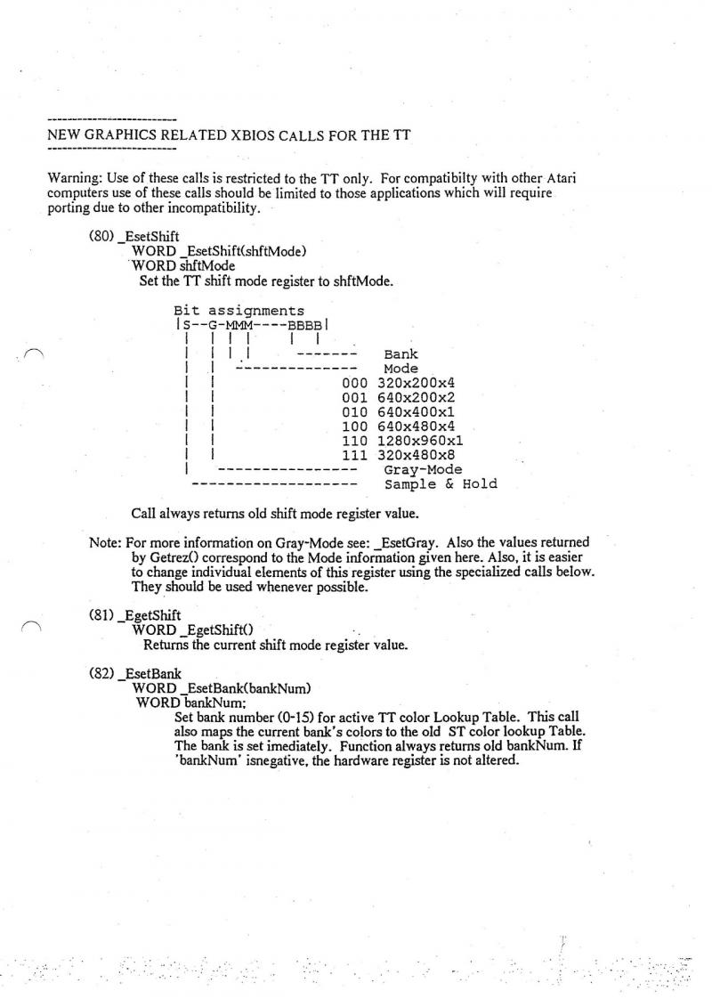
If there is more ST RAM, the TPAsize field is taken into account. If there is 622K of alternative RAM available, or more, the program loads into alternative RAM. If not, it loads into ST RAM.
In this example, it's possible that there isn't 622K of STRAM available either. If there is more than 11OK, though, the program will still be loaded and run: the TPAsize field is not considered an absolute minimum for the program to load. 110K is the program's declared text+data+bss size: that. plus space for a small initial stack, is the absolute minimum.
Remember, TPAsize does not reflect the maximum or minimum size of the TP A the program will ultimately get. It's just the tiebreaker in the case where there is more STRAM than alternative RAM, and GEMDOS has to know where to put the program.
WHAT'S IT ALL MEAN?
There are two common memory models for programs on the Atari ST. One has the user or library declare a "stack size" at compile time or link time. The runtime startup moves the stack pointer to the end of the program plus the stack size and uses Mshrink to give the rest of the TPA back to GEMDOS. Then, as the program calls the library malloc(), it uses Malloc to get memory back from the OS. For this kind of program, the TPAsize field should represent at least as much space as the "stack size" the startup will use. MWC, GCC, Turbo C. and lots of other environments use this memory model.
The other memory model keeps some amount of memory, and that memory is used as a "heap" -- the stack grows down from the top of it, and library malloc() calls use memory up from the bottom. For this kind of program, the TPAsize field should be the minimum reasonable size of the stack+heap space. Alcyon C uses this memory model.
You may wonder why these fields are part of the program header, and not controlled by, say, new GEMDOS calls, or new parameters to Pexec. The reason is that they are properly part of the program: a program's alternative-RAM characteristics and memory requirements are inherent in its behavior. They're not based on its parent's behavior, and its parent should not have to know about them in order for GEMDOS to make intelligent decisions.
Since the information is in the program's header, it can be changed by an outside utility without special knowledge of the program's structure. If you can see that a program doesn't do screen-flipping or talk to the DMA chip directly, it can probably be run in alternative RAM, and you could set its flags appropriately.
AFTER YOUR PROGRAM LOADS
The bit in the program header which controls the eligibility of alternative RAM for Malloc calls is intended for compatiblity, so existing programs which have no knowledge of alternative RAM can get the benefit of the higher speed and extra capacity.
New programs, written after the publication of this information, can use a new call, Mxalloc():
GEMDOS CALL Ox44: Mxalloc
LONG Mxalloc(amount, mode)
LONG amount;
WORD mode;
This call works like Malloc(), but takes an extra parameter: a flag telling where to get the memory.
 MODE MEANING
   0  STRAM only
   1  alternative R A M only
   2  either, ST RAM preferred
   3  either, alternative RAM preferred
If 'amount' is -lL, the size of the largest single block of the type specified by 'mode' is returned. In that case, 'mode' values 2 and 3 are identical, and the size of the largest block of either type is returned.
If 'amount' is not -IL, and a block of that size is available in the type(s) of memory specified by 'mode', the block is allocated and its starting address is returned.
It should be clear that the Malloc() call devolves into a Mxalloc() call with a 'mode' value of 0 or 3, depending on the state of the Malloc-eligibility bit in the program's header.
**********************************************************************
NEW XBIOS CALLS
XBIOS Ox2a: DMAread
Ox2b: DMA write
long DMAread(sector.count.buffer,devno)
long sector;
word count;
void *buffer;
word devno:
Reads sectors from the device into memory. Works for ACSI and SCSI devices. For SCSI, does not actually use DMA: handshakes the bytes across. Device numbers are:
$0-$7 ACSI devices $0-$7
$8-Sf SCSI devices $8-Sf.
other reserved for future use
Returns a BIOS error code.
DMAwrite is the same, but writes sectors. These calls assume that the memory at 'buffer' can actually be accessed by the bus the device is on. Therefore, DMAread from an ACSI device into alternative RAM won't work.
---------------------------------------------------------------------
XBIOS call Ox2e: NVMaccess
WORD NVMaccess(op,start,count,buffer)
WORD op, start, count;
BYTE *buffer;
This call manages the non-volatile memory (NVM) in the TT's real-time clock chip. There are 50 bytes of memory there, of which two are reserved at the end as a check on the rest of the data. This call validates the check data on reads, recomputes the check data on writes, and initializes the check data if you want.
 OPCODE MEANING
    0   READ: copy data from NVM to the buffer.
    1   WRITE: copy data from the buffer to NVM.
    2   INIT: zero the NVM.and initialize the check data.
'start' specifies the first location to read or write; 'count' specifies the number of bytes to transfer.
Returns zero for success. EBADRQ (-5) for a range error in the arguments, and EGENRL (- 12) if the NVM check data isn't consistent before a read or write. In the case of a read the data is transferred anyway.
NVM usage is to be dictated by Atari. We will take suggestions and applications for assignments of bytes, but using bytes or values whose meanings are not published by us assures trouble in the future.
OTHER IMPORT ANT NOTES
The Line-A graphics interface is maintained for backward compatibility with existing ST programs only. It should not be used for new programs. It will not keep pace with future hardware or software improvements. The VDI should be used.
This document describes the new XBIOS call, Bconmap(), which makes the new serial ports on a TT030 accessible to programs which were written when there was just one serial port.
There are new Bconin/out/stat/ostat device numbers on a TT:
 devno meaning
   0   PRN
   1   currently-mapped serial port (see below)
   2   CON
   3   MIDI
   4   IKBD
   5   RAW
   6   ST-compatible serial port (called Modem 1; default).
   7   SCC Channel B (Modem 2 on the back of a TT).
   8   TTMFP serial port (3-wire, Serial 1).
   9   SCC Channel A (full handshake, Serial 2).
Bcon calls on device 1 (normally AUX) might actually refer to any of these devices, or to a user-installed device (with an even higher devno). You use Bconmap to change the mapping of device 1. Bconmap also changes the mapping of Rsconf() calls, and of Iorec calls with Iorec device number 0.
The port assignments above are for TT only; other machines with "extra" serial ports will have other assignments. Port 6 is always going to be the ST-compatible one, though. Other devices may be installed by drivers at boot time (or even later).
**********************************************************************
XBIOS call 44 C0x2c)
LONG Bconmap(devno)
WORDdevno;
This call maps "devno" in as Bcon* device number 1. It returns the old mapping. If devno is -1, there's no change: the current mapping is simply returned. If devno is -2. a pointer is returned (see below). Legal values are -1 (for no change), -2 (to return the pointer), and values 6 and up.
You can tell you're on a system which doesn't support Bconmap by making the call and checking the return: if the return value is 44 C0x2c, the same as the XBIOS call number) then Bconmap is not available.
In addition to the above, if devno is -2. a pointer to the device mapping structure is returned. This is used by programs which need to install new mappable handlers. It also contains the number of mappable devices; the highest legal devno value for Bcon calls (including Bconmap itself) is that number plus 5.
Illegal values (0-5, or higher than the highest legal value, or negative but not -1 or -2) don't change anything, and return 0.
The mapping is accomplished by writing into the (published) vector table in low memory. In addition, new pointers are used to make Ioree and Rsconf indirect. Tlterefore, programs which use the vector table in low RAM and/or Ioree and Rsconf will see the "currently-mapped" device when they make Bcon calls with devno=l, and when they make Iorec and Rsconf calls.
Bconmap-aware programs can use the higher devno values to get at a.specific port, no matter what the current mapping is. They still need to use Bconmap to "map in" the desired port before making Iorec and Rsconf calls.
INSTALLING NEW BCONMAP DEVICE DRIVERS
Bconmap(-2) returns a pointer to a structure. The structure looks like this:
 struct bconmap {
      LONG *maptab;    /* ptr to map table (see below) */
      WORD maptabsize; /* number of lines in the table */
 };
The map table contains a line for each device. Each line contains pointers to the Bconstat, Bconin, Bcostat, and Bconout routines, plus a pointer to the Rsconf routine, plus a pointer to the Ioree for that device. The table's size (the number of devices) is in maptabsize. Maptabsize is used by all Bcon calls to range-check the device number. The highest legal value for Bcon calls (including Bconmap) is this number plus 5.
A Bconmappable driver must have Bconstat, Bconin, Bcostat, and Bconout entry points, plus an iorec, plus an Rsconf function pointer. You install it by copying the table pointed to by maptab into a larger area an,d adding your driver's entry (five procedure pointers and an iorec pointer), then changing maptab and maptabsize.
In the unlikely event that your program finds itself installing the 38th device, that is, the one which would have Bconmap number 44 (decimal), you should actually allocate TWO new rows for maptab, install your device in the SECOND one, and increment maptabsize by two. Otherwise, a current mapping of device 44 would be indistinguishable from the case where Bcorunap was not available at alL No programs should be told to use device number 44.
BCONMAP AND RSCONF
Rsconf has been mis-documented for some time. It actually returns a longword value. That longword is four bytes stuck together. Those four bytes are the UCR. RSR. and TSR registers of the MFP, plus a useless byte. The UCR register is in the high byte of the returned longword, followed by the RSR, then the TSR, and the useless byte in the low-order byte. These bytes are the values of those registers BEFORE the changes dictated by the arguments to Rsconf.
In addition, ever since Rainbow TOS, Rsconf(-2,-l,-1,-1,-l,-1) returns the last baud-rate value set with Rsconf. If the first argument is -2. all the other arguments are ignored.
In the world of Bconmap, the Rsconf arguments have to be interpreted slightly differently. Not every device is a 68901 MFP any more. For the new devices, the bits which make sense are used, the others discarded.
Programmers should use Rsconf(-I.-I.-I.-I.-I.-1) to read the current values, then change the bits they want to change and call Rsconf again with the new values;.changing bits in registers not listed below is now considered illegal. (Consider a REAL MFP: TSR contains, among other things, the transmitter enable bit; if you write Ox08 to cause a break, you will be disabling the transmitter!)
The bits in the Rsconf args and return value which Bconrnappable devices must emulate are as follows:
UCR:
bits 6-5: word-length (00=8, 01=7. 10=6, 11=5)
bits 4-3: stop bits: (01=1. 10=1.5, 11=2; 00 is invalid)
bit 2: parity (O=no, 1=yes)
bit 1: parity (O=odd, 1=even, meaningful only if bit 2 is 1)
RSR:
none
TSR:
bit 3: break (sends break while 1)
SCR: none
Programs which use synchronous modes probably talk directly to their hardware, so it doesn't make much sense to "emulate" that here. If a legal value is inconvenient (such as 1.5 stop bits with hardware which doesn't support it, or a baud rate you can't support) you can ignore it: users will get used to the restrictions imposed by your device and driver.
*******************************************************************
SCC channel A is shared between the DB9 on the back of the TT030 (labelled Serial 2) and the round LAN connector on the left side. Initially, it is programmed to use the DB9 connector.
The selection can be made as follows:
 Select LAN connector: Offgibit(Ox7f); /* clear bit 7 (only) */
 Select DB9 connector: Ongibit(Ox80);  /* set bit 7 (only) */