Copy Link
Add to Bookmark
Report
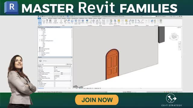
Revit: Keyboard Shourtcut commands

Keyboard Shourtcut commands
ANNOTATE
- DI ALIGNED DIMENSION / Creates an aligned dimension
- DL DETAIL LINE / Creates view-specific lines
- EL SPOT ELEVATION / Display the elevation of a selected point
- FR FIND/REPLACE / Find a replace
- GP MODEL GROUP: CREATE GROUP: DETAIL GROUP: CREATE GROUP / Creates a group of elements
- RT TAG ROOM; ROOM TAG / Tags the selected room
- TG TAG BY CATEGORY /Applies tags to elements based on their categories
- TX TEXT / Adds Text
ANALYZE
- AA ADJUST ANALYTICAL MODEL / Adjust the analytical model of the structural member in relation to those of the elements to which it joints
- DC CHECK DUCT SYSTEM / Examines the mechanical systems in a project to verify that each system is assigned to a user-defined system, and properly connected
- EC CHECK CIRCUIT / Verifies all circuits for proper connections to panels and valid system assignments
- LD LOADS / Applies point, line and area loads to a model
- LO HEATING AND COOLING LOADS / Prepares a heating and cooling load analysis report based on an existing building model
- PC CHECK PIPE SYSTEMS / examines the piping systems in a project to verify that each system is assigned to a user-defined system, and properly connected
- PS PANEL SCHEDULES / Generates a panel schedule for a specific panel
- RA RESET ANALYTICAL MODEL / Restores the analytical model alignment methods to auto-detect
ARCHITECTURE
- CL COLUMN; STRUCTURAL COLUMN / Adds a vertical load-bearing element to the building model
- CM PLACE A COMPONENT / Place a component
- DR DOOR / Adds a door to the building model
- GR GRID / Places column grid lines in the building design
- LL LEVEL / Places a level in view
- RM ROOM / Creates a room bounded by model elements and separation lines
- RP REFERENCE PLAN / Creates a reference plane using drawing tools
- RT TAG ROOM; ROOM TAG / Tag the selected room
- SB FLOOR: FLOOR STRUCTURAL / Adds structural floors to a building model
- WA WALL: WALL ARCHITECTURAL / Creates a non-bearing wall or a structural wall in the building model
- WN WINDOW / Places a window in a wall or skylight in a roof
CREATE
- CM PLACE A COMPONENT / Place a component
- DI ALIGNE DIMENSION / Creates an aligned dimension
- FR FIND / REPLACE / Find and replace
- GP MODEL GROUP; CREATE A GROUP; DETAIL GROUP: CREATE GROUP / Creates a group of elements
- LI MODEL LINE; BOUNDARY LINE; REBAR LINE / Places a new line
- LL LEVEL / Places a level in view
- MD MODIFY / Enters selection mode to select elements to modify
- PP or CTRL-1 or VP PROPERTIES; TOGGLE PROPERTIES PALETTE / Toggles the Properties Palette
- RP REFERENCE PLANE / Creates a reference plane using drawing tools
- TX TEXT / Adds text
MANAGE
- ES MEP SETTINGS: ELECTRICAL SETTINGS / Accesses dialog box to specify wiring parameters, voltages definitions, distribution systems, cable tray and conduit settings, cable tray and conduit settings, and load calculation and circuit numbering settings
- MS MEP SETTINGS: MECHANICAL SETTINGS / Accesses dialog box to configure component sizes, and the behaviour and appearance of the mechanical systems
- SU ADDITIONAL SETTINGS: SUN SETTINGS / Opens the sun settings dialog box
- UN PROJECT UNITS / Opens the Project Unit Tools
MODIFY
- AL ALIGN / Align one or more elements with selected elements
- AR ARRAY / Creates a linear or radial array of selected elements
- CO or CC COPY / Copies selected element(s)
- CP COPE; APPLY COPING / Applies copying to steel beam or columns
- CS CREATE SIMILAR / Creates an element of the same type as the selected element
- DE DELETE / Removes selected element(s) from the building model
- DI ALIGNED DIMENSION / Creates an aligned dimension
- DM MIRROR – DRAW AXIS / Reverses the position of a selected model element, using a user-generated line as the mirror axis
- EH HIDE IN VIEW: HIDE ELEMENTS / Hides an element from view
- EL SPOT ELEVATION / Display the elevation of a selected point
- EOD OVERRIDE GRAPHIC IN VIEW: OVERRIDE BY ELEMENT / Changes the graphic display settings for selected elements in the current view
- LI MODEL LINE; BOUNDARY LINE; REBAR LINE / Places a new line
- LW LINEWORK / Overrides the line style of selected line in the active view only
MODIFY
- MA MATCH THE PROPERTIES / Opens the Match Type tool to convert one or more elements to match the type assigned to another element
- MM MIRROR – PICK AXIS / Reverses the position of a selected model element, using a selected line as the mirror axis
- MV MOVE / Moves a selected element
- OF OFFSET / Moves a selected model line, detail line, wall or beam a specified distance perpendicular to its length
- PN PIN / Locks a model element in place
- PP or CTRL-1 or VP PROPERTIES; TOGGLE PROPERTIES PALETTE / Toggles the Properties Palette
- PT PAINT / Opens the Paint Tool
- RC COPE: REMOVE COPING / Removes coping
- RE SCALE / Resize the selected element
- RO ROTATE / Rotates selected elements around an axis
- RP REFERENCE PLANE / Creates a reference plane using drawing tools
- SF SPLIT FACE / Divides the face of an element into regions for application of different materials
- SL SPLIT ELEMENT / Cuts an element (such as a wall or line) at a selected point
- TR TRIM / EXTEND TO CORNER / Trims or extend one or more elements to form a corner
- UP UNPIN / Unpins an element that is locked in position or an element that is driven by its host system
- VH HIDE IN VIEW: HIDE CATEGORY / Hides an element category from view
NAVIGATOR BAR
- 32 2D MODE / Navigates the view using only 2D navigation options
- 3F FLY MODE / Simulates flying through a model
- 3O OBJECT MODE / Navigates and reorients the view in the direction of the controller cap
- 3W WALK MODE / Simulates walking through a model
- ZA ZOOM ALL TO FIT / Zooms to fit all in view
- ZE or ZF or ZX ZOOM TO FIT / Zoom to fit
- ZO or ZV ZOOM OUT (X2) / Zooms out the project view by 2X
- ZP or ZC PREVIOUS PAN / ZOOM / Returns to previous pan or zoom
- ZR or ZZ ZOON IN REGION / Zooms to a region
- ZS ZOOM SHEET SIZE / Zooms to sheet size
SNAPS
- PC SNAP TO POINT CLOUDS / Snaps to point cloud
- SC CENTERS / Snaps to center
- SE ENDPOINTS / Snaps to endpoints
- SI INTERSECTIONS / Snaps to midpoint
- SN NEAREST / Snap to nearest
- SO SNAPS OFF / Turns snaps off
- SP PERPENDICULAR / Snaps to perpendicular
- SQ QUADRANTS / Snaps to quadrant
- SR SNAP TO REMOTE OBJECTS / Snaps to objects that are not near the element
- SS TURN OVERRIDE OFF / Turns off override feature
- ST TANGENTS / Snaps to tangent
- SW WORK PLANE GRID / Snaps to the work plane grid
- SX POINTS / Snaps to points
STRUCTURE
- BM STRUCTURAL FRAMING: BEAM / Adds a load-bearing structural beam element to the building model
- BR STRUCTURAL FRAMING: BRACE / Adds diagonal members that are connected to beams and columns
- BS STRUCTURAL BEAM SYSTEM; AUTOMATIC BEAM SYSTEM / Creates a layout that is used to control the number and spacing of a series of parallel beams
- CL COLUMN; STRUCTURAL COLUMN / Adds a vertical load-bearing element to the building model
- CM PLACE A COMPONENT / Place a component
- FT STRUCTURAL FOUNDATION: WALL / Creates a wall foundation for the building model
- GR GRID / Places column grid lines in the building design
- LL LEVEL / Places a level in view
- RN REINFORCEMENT NUMBERS / Defines or edits numbering sequences by partition for rebar and fabric sheets
- RP REFERENCE PLANE / Creates a reference plane using drawing tools
- SB FLOOR: FLOOR: STRUCTURAL / Adds structural floor to a building model
- WA WALL: WALL: WALL: ARCHITECTURAL / Creates a non-bearing wall or a structural wall in the building model
SYSTEM
- AT AIR TERMINAL / Places a register, grille or diffuser
- CM PLACE A COMPONENT / Place a component
- CN CONDUIT / Draws a rigid conduit run
- CT CABLE TRAY / Draws a cable tray run
- CV CONVERT TO FLEX DUCT / Converts a section of rigid duct to flexible duct
- DA DUCT ACCESSORY / Adds duct accessories, such as dampers, in duct systems
- DF DUCT FITTING / Places duct fittings (elbows, tees, end caps, and so on) in duct system
- DT DUCT / Draws ductwork in the building model
- EE ELECTRICAL EQUIPMENT / Places electrical equipment, such as panels and switch gear
- EW ARC WIRE / Draws an arced wire run
- FDFLEX DUCT / Draws flexible ductwork in the building model
- FP FLEX PIPE / Draws flexible pipes
- LF LIGHTING FIXTURE / Adds a lighting fixture elements
- ME MECHANICAL EQUIPMENT / Places mechanical equipment such as boilers, furnaces or fans
- NF CONDUIT FITTING / Places conduit fittings
- PA PIPE ACCESSORY / Adds pipe accessories
- PF PIPE FITTING / Draws a pipe fitting in a piping system
- PI PIPE / Draws rigid piping
- PX PLUMBING FIXTURE / Places a plumbing fixture
- RP REFERENCE PLANE / Creates a reference plane using drawings tools
- SK SPRINKLER / Places a sprinkler
- TF CABLE TRAY FITTING / Places cable tray fittings
VIEW
- FN9 SYSTEM BROWSER / Finds components that are not assigned to a system
- KS KEYBOARD SHORTCUTS / Assigns key sequences to tools
- PP or CTRL-1 or VP PROPERTIES; TOGGLE PROPERTIES PALETTE / Toggles the Properties Palette
- RD RENDER IN CLOUD / Renders 3d views online
- RG RENDER GALLERY / Enables access to multiple versions of renderings, render images as panoramas, change rendering quality, and apply background environments to rendered scenes
- RR RENDER / Creates a photorealistic image of the building model
- TL THIN LINES / Displays all lines on the screen as a single width, regardless of zoom level
- VG or VV VISIBILITY / GRAPHICS / Controls the visibility and graphic display of model elements, datum elements, and view-specific elements for each view in a project
- WC CASCADE WINDOWS / Arranges all open windows in a series in the drawing area
- WT TITLE WINDOWS / See all open views at the same time
VIEW CONTROL BAR
- CX TOOGLE REVEAL CONSTRAINT MODE / Toggles the constraints in a view
- GD GRAPHIC DISPLAY OPTIONS / Opens the Graphics dialog box
- HC HIDE CATEGORY / Hides all selected categories in the view
- HH HIDE ELEMENT / Hides an element from view
- HI ISOLATE ELEMENT / Isolates selected elements
- HL HIDDEN LINE / Displays the image with all edges and lines drawn except those obstructed by surfaces
- HR RESET TEMPORARY HIDE / ISOLATE / Restores any temporarily hidden elements or categories
- IC ISOLATE CATEGORY / Isolates selected categories
- RD RENDER IN CLOUD / Renders 3D views online
- RG RENDER GALLERY / Enables access to multiple versions of renderings, render images as panoramas, change rendering quality, and apply background environments to rendered scenes
- RH TOGGLE REVEAL HIDDEN ELEMENTS MODE / Toggles to Reveal Hidden Elements Mode
- RR RENDER / Creates a photorealistic image of the building model
- RY RAY TRACE / Opens Ray Trace visual style, enabling a photorealistic rendering model that allows spanning and zooming around the model
- SD SHADED WITH EDGES / Applies a shaded edge
- WF WIREFRAME / Display the image of the model with all edges and lines drawn but with no surfaces drawn