Chamelion Modification Chip Info

No adhesive tape, no hassle.
The market of modification roms has exploded quickly, but to avoid confusion, this chip will work on all machines, whether it be a NTSC, PAL or Japanese machine. It will work with early models, the very latest models, the models that other chips just cant handle. Physically this chip looks like other chips on the market, but the coding is different.
The kit comes complete with the 14 pin chip, anti-static foam, 10 core cable, a six page instruction guide and three scanned pictures of a completed board and chip.
The price for one kit is £40 to the UK delivered, or £45 to the rest of the world, also delivered.
The chip is made in the UK and we can produce to order. So, if you just require one kit, or are in the trade and require 500, then we can cater to your needs. We do not have a delay in sending the chips out as we are not reliant upon imports.
We accept Visa, Mastercard, Eurocard, Switch and Delta. You can order direct by emailing your details using the form provided, or by calling / faxing us on 0181 4883413. You might have some questions before ordering, so please feel free to email us: boom@moss.demon.co.uk
Instructions
Kit contents:
1. Chip
2. Multi core wire.
3. Instructions to fit.
4. Picture of board
5. Enlarge picture of board section
6. Picture of chip.
7. Disclaimer and warning - Please read.
Introduction
Thank you for purchasing the Chameleon Chip. Please read carefully everything in this document and study the pictures, which accompany the instructions before you start. It can be painless to install this chip, but there are points you need to be very careful about, so don't rush it. Before you start, clear a space where you will be comfortable and have to hand a soldering iron, solder (flux too if the solder isnt self fluxing.), wire stripper or cutter, screwdriver and insulating tape. You should also have a container to place the screws into.
Disclaimer and Warning
Opening the Playstation WILL invalidate your warranty. So, if there is any warranty left on the machine, please remember this point. If you are not confident with a soldering iron, please get someone who is to do this job. A competent user should take less than 15 minutes to complete this fitting. We will not accept any liability whatsoever for the damage of your Playstation as a result of installing this chip. The chip has been tried and tested, but incorrect installation could possibly result in damage. Always remember to take steps to avoid static. Obtain a wrist band designed to remove static if necessary. Please remember to disconnect the machine from any POWER source before opening or working on the internals of any electrical item. This chip is not designed as an official product to be used with the playstation. Playstation is a trademark of the Sony Corporation.
Instructions
STAGE 1 - Taking the PSX apart
- You will have to remove all the screws of the machine from the underside to take off the cover. Remove top cover to reveal the laser mechanism.
- To remove the laser mechanism, first look to the left and you will find 3 connectors, 2 to the main PCB and 1 to the separate power PCB. The brown/orange ribbon is very delicate. You can not obtain spares for the PSX, so be so very very careful removing this item. It pays to take lots of time. The ribbon is connected to the board via a black oblong connector. DO NOT just pull the ribbon out IT WILL TEAR and the whole laser will be useless. The connector lifts up at both ends and clicks. Do not be alarmed if the top of the connector comes off, but you really should not use that much force. You need just to lift the ends to remove the ribbon. If you find yourself using any amount of force you have not lifted the connector and are liable to rip the ribbon. I am pressing the point as this is the most delicate part.
- The other connector (white) will come out easily. The connector on the power PCB will also come out easily. Remove them both.
- The laser mechanism will now lift off of the metal plate via 3 prongs. Please note the position for re-fitting.
- Put the laser in a safe position.
- Remove the screws from the main metal cover and the ones near the front of the machine holding down the controller ports.
- Remove the controller ribbon from the PCB. It is not quite so delicate at the laser one, but be careful anyhow.
- Remove the metal controller port covers and the controller ports themselves. Put them in a safe place.
- Remove the main metal cover to reveal the PCB.
- Remove the PCB and turn it over.

STAGE 2 - Soldering
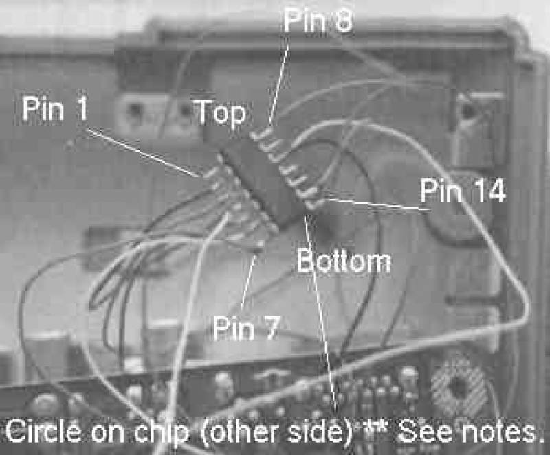
I am not here to teach you to solder, because if you can't, stop here and get someone who can. I am going to remind you quickly again that static can blow chips. Eliminate static. Please refer to the picture of the chip supplied. There are 14 pins, not all of which are used. The picture shows the legs of the chip bent. This is for the picture. The legs are quite sturdy, but excessive force may break them. If you study the actual chip supplied you will notice a couple of things. Firstly one end has been severed. Do not be alarmed, this is normal. On the underside of the chip there is a circle. As you will see from our picture, we ask you to have the chip with the circle at the bottom and hidden (the bottom if you like) for the sake of identifying the pins from 1-14. The severed part should therefor be at the top.
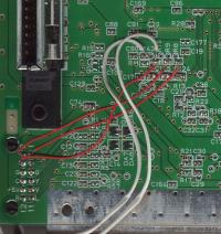
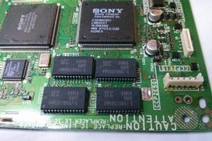
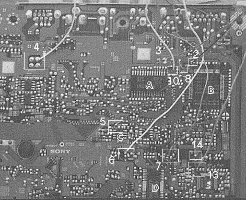
The top left pin we will call pin 1. The top right we shall call pin 8. The pins run from top left to the bottom 1 to 7 and then top right from 8 to 14 in my instructions. In the main PCD picture, you will see the solder points 2,3,4,5,6,7,8,10,13,14 as only 10 pins are used. I will describe the solder points, using the numbers. You will also notice that I have labelled 5 chips A,B,C,D AND E for reference purposes too. The picture together with the description should make the process fairly easy. You should have the board with the composite outputs to the top. The sony stamp in the middle (gold one) should read the right way up. Use enough wire so you can solder one end, run it around the other side of the board, so you can have the chip on the top side.

PINs
Pin 1 - Not used
Pin 2 - This has to be soldered near chip B. The solder point is just right of a small resistor and joins the first leg of chip B if you follow the track. Basically it is the first blob on the row of blobs above chip B. Quite easy to locate from the picture.
Pin 3 - Just above the row of solder blobs above chip A. It is between two resistors and directly above the last blob on the top row for chip A. Again, easy to find.
Pin 4 - Easy. Look at the picture of the board, you will find it. Top right of 4 blobs to the left of centre of the PCB. Remember my picture is not the whole board.
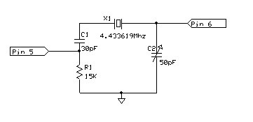
Pin 5 - Locate chip C, the smallest of the 5 chips marked. This point is on the top left. There is a blob just above the chip, but the one you are looking for is just above THAT and slightly to the left.
Pin 6 - Below chip C there are 2 groups of blobs, one set of 5 to the left and one of 5 to the right. Locate the right hand set. You want the top left one in this group. Refer to the picture.
Pin 7 - One of the harder ones to find. Above chip D there is a set of blobs then just to the right there is another set. The right set is what you need. The solder point is not the first 2 on top of each other, but the 3rd on its own. You will notice from the square in the picture I highlight 5 points. The point you want is 3rd from the right in that square.
Pin 8 - Locate chip B. Locate the legs on the left hand side of the chip. The solder point is the first blob you come to if you follow the track from the top leg on the chip. Again refer to the pic for the general location. The actual solder blob dosnt show up too well in the picture as the wire is green (the same colour as the PCB.)
Pin 9 - Not in use.
Pin 10 - Once you have located Pin 8, track left a bit and you will see a small resister. Track left again and find the next one. This next one is the solder point for pin 10.
Pin 11 - Not in use.
Pin 12 - Not in use.
Pin 13 - Locate chip E. Locate the first leg, on the top of the chip. The block connected by a track to this leg is the solder point for pin 13.
Pin 14 - Immediately above the point for pin 13 is the blob for pin 14. Easy to find.
Thats it for the soldering. We suggest once you complete this work and the Playstation loads games using this chip, then insulate the chip and tape it in an empty space on the power PCS (left one...the thin long one.)
Finishing Up
All that remains now is to carefully put the PSX back together. If the playstation does not work, ie the disk doesn't spin, or there is no picture or no sound...don't panic. You have probably either soldered the wrong pin to the wrong point, or the wire is not properly fixed to the pin of the chip, or the solder point. You should check that the chip is the right way up, and that pin 1 is pin 1 from my picture. Run back through the solder points and check you have soldered everything in the right places. I have sold chips before creating this instruction list, and people used to draw a diagram in pencil to take a reference home with them. The chips always worked...so, you have a step by step account, so use it. It will eliminate most problems.
Please check everything several times before contacting me. You have probably made an error if the chip isn't working. They are tested before being shipped. We will replace it should it not be working when received, providing we are satisfied it was not caused by your neglect. Please enjoy the product and let us know how you get on.
Now, start the installation....as I know you have been sensible and read this all the way through before starting....yes?