Intro to 3D Graphics - Volume 02

Intro to 3D Graphics - Volume 02
Greetings
Welcome back everyone,
It's time for the second article in the 3D series, in which we cover another basic element of a 3D system... something seen in nearly ever demo for the past few years that involves vectors at all. Rotation. Whether it be that nice texture-mapped stone from Valhalla's "Solstice", or just a flat-shaded cube from a 4k intro, things rotate almost constantly. So it's time to start performing some rotations on our own. :-)
I'm going to keep this article relatively short (along with the subsequent ones)... after all, Snowman has more to put in DemoNews than my constant rambling, and I can't keep sucking up all the space like this. ;) Nonetheless, I hope you find this article useful, as we continue our drive toward learning 3D graphics.
Ready? Well like it or not, here we go! :)
Section One - 2D Rotation
Before we can get more sophisticated 3D rotations going, we need to try it in two dimensions first... because 3D rotations are just based on three 2D rotations, but combined.
So how do we rotate something in 2D? How do we take any 2D point, give it an angle to rotate by about the origin, and get it correctly to its new position? Well this is where that Trig knowledge from the first article comes into play.
Everything about rotation involves Trig. Sine and Cosine are very much your friends here. And it's not that complicated, really... you can rotate in one plane with only 4 multiplies (other optimizations come later as well).
So how do we go about this? Well, let's take it piece by piece. First, I'll assume the XY plane (the real one, where Y goes up) for this, as we try to take a point and rotate it.
A lot of docs, when trying to explain rotation, will give you the simple equations for it but give you no clue as to how those equations came about. Several people have asked me, "Hey, if and when you ever do a 3D tutorial, tell me how the heck you get those rotation equations, cuz I have no idea where those came from and why they work."
Well, I can't quite tell you where they came from at first (like who thought of them), but I can replicate the ideas here and show you what makes sense to me. If it makes sense to you to, then I guess it worked. :-)
Here's the idea...
Get out a piece of paper. No, don't worry, this isn't a quiz. ;)
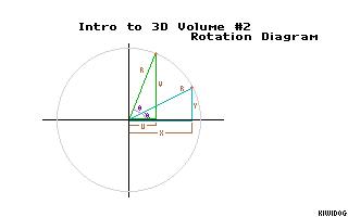
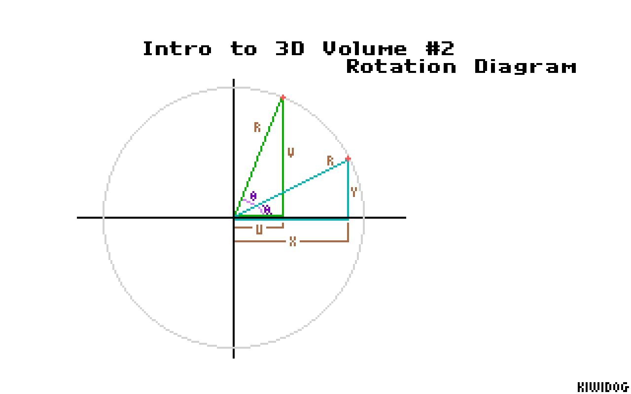
On the paper, draw a pair of conventional XY coordinate axes, and then lightly sketch a large circle on it. Make sure the circle is light; you don't really need it for much except placing a couple points.
After you draw the circle, put a point at about, say, 30 degrees (assuming 0 degrees is to the right and the angles go counterclockwise). Then put another point at about 70 degrees, in the same fashion. We're going to pretend that the first point is our original point, and that we're trying to rotate it to the second point, our destination... a rotation of 40 degrees about the origin. The actual accuracy of the points doesn't matter; if you're a bit off, it's fine.
Now with each point, draw a triangle for that point. Each triangle's three sides are the X axis, the the line from the origin to the point, and the line from the point straight down to the X axis. What you should have now are two right triangles in the upper right quadrant of your XY plane, one being pretty upright (the destination point's), and the other a bit more wide than tall.
Time for some labels... okay, for each triangle, label the line going from the origin to the point as "R" (for radius). Since it's the same length for both triangles, we use the same label. Now, on the first triangle (the short, wide one), label the side along the X axis "X", for that length. Likewise, label the line from the X axis up to the point as "Y" for that height.
For the second triangle (the tall one, for the 70 degree point), label the X length and Y height as "U" and "V", respectively, in a similar fashion.
Finally, we need two angles. In the angle between the X axis and the first, lower R side (30 degrees), label it í (called Phi). Then label the angle between the lower R and the higher R (the one at 70 degrees) as é (called Theta).
There we go... we've got our drawing. :-) If my little walkthrough in drawing this has confused you to no end, either try it again from the beginning, or look at the PCX in this supplement, with an image of the same diagram I'm describing.
Okay, so we have this drawing. Basically, what we know in the beginning is that we have this initial point at an unknown angle (we know it's 30 degrees in this example, but normally, you won't know that for arbitrary points), yet we know it has Cartesian coordinates (X,Y). What we want to do is pump X and Y through an equation or two, along with the angle we want to rotate by (which we labeled as Theta, and in this example is 40 degrees), and find out its new coordinates, called (U,V). So what equations do we use? Let's find out...
There are several convenient identities in Trigonometry that you can find in pretty much every math textbook with Trig in it.... one of those identities is called the "Law of Sines", which goes like this...
Where A, B, and C are the lengths of the sides of a triangle, and α, β, and γ are the angles _directly opposite_ those sides...
	    /|
	   /β|
	C /  |
	 /   |A
	/    |
       /     |
      /α    γ|
      --------
	  B
It doesn't have to be a right triangle; it works for every triangle there is. Granted, for our purposes, we _will_ be using our right triangles, and this will help us out.
Now if we use our first right triangle, the short one, and pretend that R is our "C" of the triangle, by the fact that this is a right triangle, we know that γ is 90 degrees. And the Sine of 90 is 1, which gives us one very nice piece of math meat.
We only need to use one other side of our Law of Sines formula in this example, in this case, the A-α side. In our case, "A" is the same as Y, and α is the same as í. So we have a little mini-formula,
	Sin(90)   Sin(í)                   1    Sin(í)
	------- = ------    which means   --- = ------
	   R        Y                      R      Y
Then, if you multiply each side by Y, it moves the Y to the left side, so
	 Y
	--- = Sin(í)
	 R
This should all make sense so far, I hope. If you're looking at the diagram as you read this, it should clear things up a bit.
Okay, so we can see the relation between the angle í, and the sides Y and R. Well since í is across from Y, shouldn't we be able to have the same kind of relation for the other triangle, with V and R? The angle across from V is just í and é added together, so shouldn't that work?
Sure does. :-)
	 V
	--- = Sin(í+é)
	 R
Okay, time for another nifty Trig identity (BTW, if you don't have a math book with all these identities in it, let me know... if enough people ask for a listing, I'll type up a quick reference list with identity equations that you can use. Just email to the address at the end, if you think you'd like that :)
Anyway, another nice identity is that for any two angles α and β,
So we sub that into our previous thing, and we have
	 V
	--- = Sin(í)*Cos(é) + Cos(í)*Sin(é)
	 R
Multiply by R now, to get V (the destination point's X value that we've been trying to find), and it's
V = R*Sin(í)*Cos(é) + R*Cos(í)*Sin(é)Welp, last identity.... this one, taken from Polar coordinates. If you've had algebra, you've used Polar coordinates before. Well if you remember the way to convert a polar point to Cartesian (I doubt you do, so I'll remind you... it's gonna take a while before you end up memorizing all these darn formulas, trust me :) those conversions are
	 X = R*Cos(Theta)     *** Don't confuse these with our R, X, or Y!
	 Y = R*Sin(Theta)         They're just conversion equations ***
Well look at our V equation above... notice anything? We know Phi is an angle in the triangle that deals only with X and Y, which we know (since they're just your first point and all). So can we drop those R*Sin(í) and R*Cos(í) parts and just sub in X and Y like you would do with Polar? You betcha.....
V = Y*Cos(é) + X*Sin(é) *** FINAL V EQUATION!!! :) ***That's all we need! Hooray! :) We know X and Y, since we started with those. And we know é, since it's the number of degrees we want to rotate by (in our example, 40 degrees). So if we use this equation, we get the V value, which is the Y coordinate of the FINAL point. :)
Now we still need to get U (the final point's X coordinate). Luckily, the series of equations is the same almost, except one identity is different. I won't work out the whole thing again, you can do that if you want. But here are the differences that you'll see. One, since we're doing the horizontal element instead of vertical,
	 U
	--- = Cos(í+é)
	 R
Now's Cosine's Sum of Angles formula is a little bit different than Sine's,
which will end up giving us that subtraction instead of addition in the end. If you keep working the equations the same as we did before, but with this new identity, you get the U equation too! :)
U = X*Cos(é) - Y*Sin(é) *** FINAL U EQUATION!!! ***Summing up those equations into nice, happy, 2D rotation form.....
	NewX = (OldX*Cos(Theta)) - (OldY*Sin(Theta))
	NewY = (OldY*Cos(Theta)) + (OldX*Sin(Theta))
And there we have it! Note that I made it very clear as to the difference between the "Old" and "New" values. It's important that you do this, too. You don't want to just use a value "X", for example.... because if you calculate the "new" X and end up using that instead of the "old" X in the second equation (for NewY), you don't get the right rotation.
IN ROTATION, USE ONLY THE OLD VALUES UNTIL ALL THE NEW ONES ARE FOUND!
Once you have the final new X and Y values, _THEN_ replace the old pair with the new pair, and go on your way. Make sure to keep the values separate until that time.
BTW... As you look back at how I derived these rotation formulas, don't feel bad if you feel like you couldn't have derived them yourself... especially if you're just beginning. I know I ran on these formulas blindly for over a year before I ended up losing them and was forced to recreate them again in this fashion. I couldn't have done it earlier. It takes time, so if you feel like you're still in the dark... don't. Eventually you'll get the hang of it all. :-)
Any more to 2D rotation? Nope, that's the whole of it. Before you try out 3D rotation (explained in the next section), test out the above principles in some of your own code, by plotting a few pixels here and there and then rotating them about the origin. It's not hard at all to turn the above formulas (formulae?) into code. Also, if you need some help or are just plain curious, I've got some example source (in both Pascal and C, just like last time) in this supplement, demonstrating this stuff. Feel free to check it out. :)
Okay, well, enough of this planar stuff.... on to 3D rotations! (And relax, there's not much more; you've done the bulk of the work already....)
Section Two - 3D Rotation
So what do we need to turn our rotations into 3D rotations? Not much, actually. There are many ways to do rotations in 3D, some simpler than others. The simplest (and most common from what I've seen) way is to do it by using three 2D rotations, one for each axis.
The 2D rotations we did in the last section are on the XY plane. But as you think about the XY plane in terms of 3D, the rotation takes on another meaning... it was also a rotation ABOUT the Z axis. Meaning that we have the Z axis, and whatever Z values the points may have, they stay the same, as we are rotating around that axis itself. The only values that change in a rotation about any axis are the values of the two OTHER coordinates.
So a rotation about Z will affect X and Y, a rotation about X will affect Y and Z, and a rotation about Y will affect Z and X. It's just one big cycle...
So if we want to do a full all-axis 3D rotation, we just arrange three back-to-back 2D rotations, one for each axis, like this...
	NewY = (OldY*Cos(ThetaX)) - (OldZ*Sin(ThetaX))  ** X axis rotation **
	NewZ = (OldZ*Cos(ThetaX)) + (OldY*Sin(ThetaX))

	(Copy NewY and NewZ into OldY and OldZ)

	NewZ = (OldZ*Cos(ThetaY)) - (OldX*Sin(ThetaY))  ** Y axis rotation **
	NewX = (OldX*Cos(ThetaY)) + (OldZ*Sin(ThetaY))

	(Copy NewZ and NewX into OldZ and OldX)

	NewX = (OldX*Cos(ThetaZ)) - (OldY*Sin(ThetaZ))  ** Z axis rotation **
	NewY = (OldY*Cos(ThetaZ)) + (OldX*Sin(ThetaZ))

	(No copies needed, since we're done)
The reasons for mid-copies are like I said; for each axis rotation you need to keep using the old values until both the new ones are done. But each axis's rotation is independent of the other two... so after each pair, you need to update all the values before going on to the next axis. You don't want to use one axis's old values when going into rotating about another axis; that would be bad.
Once you've done all three axes, you should have your new point, completely rotated about each angle as you wish (ThetaX, ThetaY, and ThetaZ).
One important point... the order in which you do these axes DOES make a difference. Rotating in an X-Y-Z sequence will not give you the same results as rotating in a Z-X-Y sequence, etc. Now, for your engine at this point, all you're probably concerned about is looks, i.e. that your object is rotating and you can see it rotating. Since that's the case, it really doesn't matter for the moment which order you do things in. It's the appearance that counts. But later on, when you get into more complex issues that involve more things than just a set of points, you'll want to keep your rotation order consistant. I just use X-Y-Z because it's pretty natural. :-)
I'm not going to get into optimizations of this rotation material until another time, but I can give you a hint or two now... first, you'll notice that right now it's at 12 multiplies for a full rotation (4 for each axis). But it turns out you can reduce it to at least 9 multiplies, by precalculating a few values at the beginning of each frame and getting a final 3x3 matrix for the actual point rotations themselves (if you don't know what I mean by matrix, don't worry about it at the moment; we'll get into matrices later on). It's something to look into, if you're curious and feel like tinkering with the math a bit.
Also, once again, this method of rotation is only one way to rotate. There are other ways, sometimes involving other coordinate systems, that can be more efficient on occasion as well. You'll discover those in time (and probably in some of the later articles :) But for now, this I think is the simplest way to begin... get these concepts down first, and drill them into your brain. You'll know when to switch gears when the time comes.
Well, looks like the end of another article! I've got some sample source in this supplement, as well as a PCX of that 2D rotation diagram, if you got lost in all of this mess. :-) Take the time to look at the code, see how it relates to the math used in here, and most importantly, DO SOME EXPERIMENTATION ON YOUR OWN. This kinda stuff isn't learned by reading, it's learned by doing.
Now go forth, plot some dots, get them spinning, and have fun! Keep watching, though... 'cause it's only gonna get better. :-)
See you next time...
Chris Hargrove
a.k.a. Kiwidog, of Terraformer & Hornet
Coding & Organization
email: <kiwidog@vt.edu>

TP_EX2.PAS
{$X+}
program TP_EX2;

{

  "Introduction to 3D Programming" Tutorial series
  Volume #2 - For DemoNews 116
  Topic: 2D and 3D Rotations

  Sample code for Turbo Pascal 7.0 or above (might work with lesser versions,
  probably at least 6.0, but it's untested so I can't guarantee anything).

  Make sure at least 286 instructions are enabled in your compiler options.

}

uses crt;


{ "vector" structure - holds a 3D cartesian point, and its projection. }

type
    vector = record
             x : integer;
             y : integer;
             z : integer;
             scrx : integer;
             scry : integer;
             end;

{virtual screen to reduce flicker.}

    virtualscreen_ray = array[0..63999] of byte;
    virtualscreen_ptr = ^virtualscreen_ray;

{ Box object, used for the last example as well as this one. }
var
   Box : array[0..7] of vector;  {The values are initialized later}

   RotatedBox : array[0..7] of vector;

   virtualscreen : virtualscreen_ptr;
   virseg, physeg : word; {segment addresses for screens}

{
videomode,putpixel,clrscr,copyscr, and wfvr functions for graphics display.
(wfvr is short for Wait For Vertical Retrace)

(Yes, these are not optimized, but that's not the point of
 this example program :-)

 (Can you sense that I'm cut-and-pasting from volume 1? :)

}

procedure videomode(mode : word); assembler;
asm
   mov ax, mode
   int 10h
end;

procedure putpixel(x, y : word; color : byte; vseg : word); assembler;
asm
   mov es, vseg
   mov ax, y
   shl ax, 6
   mov bx, ax
   shl ax, 2
   add ax, bx
   add ax, x
   mov di, ax
   mov al, color
   mov [es:di], al
end;

procedure clrscr(screenseg : word); assembler;
asm
   mov es, screenseg
   xor di, di
   xor ax, ax
   mov cx, 32000
   cld
   rep stosw
end;

procedure copyscr(destseg, srcseg : word); assembler;
asm
   push ds
   push si  {I've had problems if I don't push SI, so it's a precaution.}
   mov ds, srcseg
   mov es, destseg
   xor si, si
   xor di, di
   mov cx, 32000
   cld
   rep movsw
   pop si
   pop ds
end;

procedure wfvr; assembler;
asm
   mov dx, 3dah
   @waitr:
   in al, dx
   test al, 8
   jz @waitr
   @retrr:
   in al, dx
   test al, 8
   jnz @retrr
end;

{  sin256 and cos256 functions.  These return the sine and cosine of angles
   in a 256-degree system (just like a regular 360-degree system, only
   256 is easier to deal with for 3D coding).  So where in a conventional
   system, 90 degrees is straight up, in this system 64 degrees is straight
   up, etc.  The sin and cos functions in C deal with radians, and these
   functions just convert from radians to the 256-degree system. }

{  Note: This is an insanely unoptimized way of doing Trig functions.  Two
   very effective optimizations you can do are
	1) Make a look-up table of all 256 sin/cos values, so actually doing
	   a sin() or cos() function isn't necessary (this is a major speed
	   gain).  I would have done it here, but I didn't want to confuse
	   you any more than I already am :)  But this is probably the FIRST
           thing you want to do in your own 3D system.
	2) Replace the floating point values with "fixed point" integer
	   values.  This makes it easy to do 3D functions in straight
	   assembler.
}

function sin256(angle : byte) : real;
begin
  sin256 := sin(angle*PI/128);
end;

function cos256(angle : byte) : real;
begin
  cos256 := cos(angle*PI/128);
end;


{
procedure RotatePoint(point : vector; var dest : vector; rx, ry, rz : byte);

This rotates the vector point in 3D by the three "theta" angles you give
in rx, ry, and rz, and puts the final rotated point in dest.  The angles
are in the 256-degree system mentioned above.

These formulas are based on the article text, so you can see how they're
applied here. :)

}

procedure RotatePoint(point : vector; var dest : vector; rx, ry, rz : byte);
var temp1, temp2 : real;
begin

  {  Since we don't want to destroy the original point (if we do, the
     rounding error over time will mess it up beyond repair), we'll keep
     it intact and use the dest point for all our operations. }

  dest.x := point.x;
  dest.y := point.y;
  dest.z := point.z;

  { X axis rotation, by 256-degree angle rx }

  temp1 := dest.y*cos256(rx) - dest.z*sin256(rx);
  temp2 := dest.z*cos256(rx) + dest.y*sin256(rx);
  dest.y := trunc(temp1);
  dest.z := trunc(temp2);

  { Y axis rotation, by 256-degree angle ry }

  temp1 := dest.z*cos256(ry) - dest.x*sin256(ry);
  temp2 := dest.x*cos256(ry) + dest.z*sin256(ry);
  dest.z := trunc(temp1);
  dest.x := trunc(temp2);

  { Z axis rotation, by 256-degree angle rz }

  temp1 := dest.x*cos256(rz) - dest.y*sin256(rz);
  temp2 := dest.y*cos256(rz) + dest.x*sin256(rz);
  dest.x := trunc(temp1);
  dest.y := trunc(temp2);

  { We're done! :) }

end;

{
procedure RotateBox(angle_x, angle_y, angle_z : byte);

This just does RotatePoint on the 8 points of the Box vector array, and
puts the resulting box in RotatedBox.  RotatedBox is what's used in the
PointProject/DrawRotatedBox combo, which is the stuff we learned in the
first volume. :)
}

procedure RotateBox(angle_x, angle_y, angle_z : byte);
var count : byte;
begin

  for count := 0 to 7 do
  begin
    RotatePoint(Box[count], RotatedBox[count], angle_x, angle_y, angle_z);
  end;
end;

{
procedure PointProject(distance : integer; point : vector,
                       var dest : vector; center : vector);

Same function as in volume #1, so you should be familiar with it by now...

}

procedure PointProject(distance : integer; point : vector;
                       var dest : vector; center : vector);
begin
     dest.scrx := (256*(point.x+center.x)
                  div (distance-(point.z+center.z)))+160;

     dest.scry := 100-(256*(point.y+center.y)
                  div (distance-(point.z+center.z)));
end;

{
procedure DrawRotatedBox(cenx, ceny, cenz : integer; color : byte);

Same as in volume #1, except it draws the RotatedBox structure, which is
created after doing the RotateBox procedure.  The putpixel was also modified
to draw to any destination screen, so in this example I used a virtual screen
to reduce flicker.  The DrawRotatedBox will draw to the virtualscreen address
and the copyscr procedure will move it to the actual screen after the
retrace.
}

procedure DrawRotatedBox(cenx, ceny, cenz : integer; color : byte);
var
   count : integer;
   BoxCenter : vector;
begin
     BoxCenter.x := cenx;
     BoxCenter.y := ceny;
     BoxCenter.z := cenz;

     for count := 0 to 7 do
     begin
     PointProject(256, RotatedBox[count], RotatedBox[count], BoxCenter);
     putpixel(RotatedBox[count].scrx, RotatedBox[count].scry, color, virseg);
     end;
end;


{
Main program - Draws a standard box like in volume 1, waits for keypress,
	       then rotates by each axis between keypresses, and finally
	       by all axes.

	       The drawing is to the virtual screen, allocated in the
	       beginning.  copyscr copies the virtual screen to the
	       physical screen, during the vertical retrace.
}

var
   angle : byte;

begin

  {set up virtual screen and physical screen addresses}
  getmem(virtualscreen, 64000);
  virseg := seg(virtualscreen^);
  physeg := $A000;

  Box[0].x := 20;   Box[0].y := 40;   Box[0].z := 30;
  Box[1].x := 20;   Box[1].y := 40;   Box[1].z := -30;
  Box[2].x := 20;   Box[2].y := -40;  Box[2].z := 30;
  Box[3].x := 20;   Box[3].y := -40;  Box[3].z := -30;
  Box[4].x := -20;  Box[4].y := 40;   Box[4].z := 30;
  Box[5].x := -20;  Box[5].y := 40;   Box[5].z := -30;
  Box[6].x := -20;  Box[6].y := -40;  Box[6].z := 30;
  Box[7].x := -20;  Box[7].y := -40;  Box[7].z := -30;

  writeln('Intro to 3D Programming - Volume #2, 2D and 3D rotations.');
  writeln('By Chris Hargrove (Kiwidog - Terraformer/Hornet)');
  writeln('From DemoNews issue #116, 2/19/96');
  writeln('This example takes the box we had from Volume #1, and performs');
  writeln('basic rotations on it.');
  writeln;
  writeln('The first rotation will be about the X axis, the second about');
  writeln('the Y axis, and the third about the Z axis.  The final rotation');
  writeln('will rotate about all three axes, at the same time.  Just press');
  writeln('a key during any rotation to move to the next one.');
  writeln;
  writeln('BTW, no this example is not optimized. ''Tis not meant to be.:)');
  writeln;
  writeln('Hit a key to begin...');
  readkey;

  videomode($13);

  repeat
        RotateBox(angle, 0, 0);
        inc(angle);
        DrawRotatedBox(0,0,0,15);
        wfvr;
        copyscr(physeg, virseg);
        clrscr(virseg);
  until keypressed;
  readkey;

  repeat
        RotateBox(0, angle, 0);
        inc(angle);
        DrawRotatedBox(0,0,0,15);
        wfvr;
        copyscr(physeg, virseg);
        clrscr(virseg);
  until keypressed;
  readkey;

  repeat
        RotateBox(0, 0, angle);
        inc(angle);
        DrawRotatedBox(0,0,0,15);
        wfvr;
        copyscr(physeg, virseg);
        clrscr(virseg);
  until keypressed;
  readkey;

  repeat
        RotateBox(angle, angle, angle);
        inc(angle);
        DrawRotatedBox(0,0,0,15);
        wfvr;
        copyscr(physeg, virseg);
        clrscr(virseg);
  until keypressed;
  readkey;

  videomode(3);
  freemem(virtualscreen, 64000);
end.
WC_EX2.C
/*

  "Introduction to 3D Programming" Tutorial series
  Volume #2 - For DemoNews 116
  Topic: 2D and 3D Rotations

  Sample code for Watcom C 10.0 or above, for 32-bit DOS.

  Compile with: WCC386 -bt=dos WC_EX2
		(other command line switches can be added if you wish)

  Link with: WLINK system dos4g file WC_EX2
	     (or use pmodew if you have it and wish to use it)

*/

#include <stdlib.h>
#include <conio.h>
#include <math.h>

#define PI 3.1415926535897932385

/* "vector" structure - holds a 3D cartesian point, and its projection. */
typedef struct vector
{
int x;
int y;
int z;
int scrx;
int scry;
} vector;

/* Box object, used for the last example as well as this one. */

vector Box[8] =  {
		 { 20, 40, 30, 0,0},
		 { 20, 40,-30, 0,0},
		 { 20,-40, 30, 0,0},
		 { 20,-40,-30, 0,0},
		 {-20, 40, 30, 0,0},
		 {-20, 40,-30, 0,0},
		 {-20,-40, 30, 0,0},
		 {-20,-40,-30, 0,0}
		 };

vector RotatedBox[8];

/*

videomode, putpixel, clrscr, copyscr, and wfvr functions for graphics display.
(wfvr is short for Wait For Vertical Retrace)

(Yes, these are not optimized, but that's not the point of
 this example program :-)

 (Can you sense that I'm cut-and-pasting from volume 1? :)

*/

/* videomode - sets the video mode */
void videomode(unsigned short int mode);
#pragma aux videomode = \
	"int 10h"	\
	parm [ax]	\
	modify [ax];

/* putpixel - draws a pixel to the destination 320x200 linear screen. */
void putpixel(unsigned int x, unsigned int y, char color, char *vseg);
#pragma aux putpixel =  	\
	"shl eax, 6"		\
	"mov ebx, eax"		\
	"shl eax, 2"		\
	"add eax, ebx"		\
	"add eax, ecx"		\
	"add eax, esi"		\
	"mov edi, eax"		\
	"mov [edi], dl"		\
	parm [ecx] [eax] [dl] [esi]	\
	modify [eax ebx edi];

/* clrscr - clears the destination screen */
void clrscr(char *screenaddr);
#pragma aux clrscr = 		\
	"xor eax, eax"		\
	"mov ecx, 16000"	\
	"cld"			\
	"rep stosd"		\
	parm [edi]		\
	modify [eax ecx];

/* copyscr - copies the source screen to the destination screen */
void copyscr(char *destaddr, char *srcaddr);
#pragma aux copyscr = 		\
	"mov ecx, 16000"	\
	"cld"			\
	"rep movsd"		\
	parm [edi] [esi]	\
	modify [eax ecx];

/* wfvr - waits for the vertical retrace */
void wfvr(void);
#pragma aux wfvr = \
	"mov edx, 3dah" \
	"waitr:" \
	"in al, dx" \
	"test al, 8" \
	"jz waitr" \
	"retrr:" \
	"in al, dx" \
	"test al, 8" \
	"jnz retrr" \
	modify [edx al];


/* Function Declarations for RotatePoint, RotateBox, and the trig functions */

void RotatePoint(vector point, vector *dest, char rx, char ry, char rz);
void RotateBox(char angle_x, char angle_y, char angle_z);
float sin256(char angle);
float cos256(char angle);

/* Declarations for PointProject and DrawRotatedBox, from Volume 1 */

void PointProject(int distance, vector point, vector *dest, vector center);
void DrawRotatedBox(int cenx, int ceny, int cenz, char color);

/* Screen pointers for the drawing functions */

char *physicalscreen = 0xA0000;
char *virtualscreen;


/*
Main program - Draws a standard box like in volume 1, waits for keypress,
	       then rotates by each axis between keypresses, and finally
	       by all axes.

	       The drawing is to the virtual screen, allocated in the
	       beginning.  copyscr() copies the virtual screen to the
	       physical screen, during the vertical retrace.
*/

void main(void)
{
  char angle;

  videomode(0x03);

  if ((virtualscreen = (char *)malloc(64000)) == NULL)
  {
    printf("\nOut of memory for virtual screen. :(\n");
    exit(1);
  }

  printf("\nIntro to 3D Programming - Volume #2, 2D and 3D rotations.\n");
  printf("By Chris Hargrove (Kiwidog - Terraformer/Hornet)\n");
  printf("From DemoNews issue #116, 2/19/96\n");
  printf("This example takes the box we had from Volume #1, and performs\n");
  printf("basic rotations on it.\n\n");
  printf("The first rotation will be about the X axis, the second about\n");
  printf("the Y axis, and the third about the Z axis.  The final rotation\n");
  printf("will rotate about all three axes, at the same time.  Just press\n");
  printf("a key during any rotation to move to the next one.\n\n");
  printf("BTW, no this example is not optimized. ");
  printf("'Tis not meant to be. :) \n\n");
  printf("Hit a key to begin...\n");

  getch();

  videomode(0x13);

  /* X axis rotation */
  while (!kbhit())
  {
    RotateBox(angle++,0,0);
    DrawRotatedBox(0,0,0,15);
    wfvr();
    copyscr(physicalscreen, virtualscreen);
    clrscr(virtualscreen);
  }
  getch();

  /* Y axis rotation */
  while (!kbhit())
  {
    RotateBox(0,angle++,0);
    DrawRotatedBox(0,0,0,15);
    wfvr();
    copyscr(physicalscreen, virtualscreen);
    clrscr(virtualscreen);
  }
  getch();

  /* Z axis rotation */
  while (!kbhit())
  {
    RotateBox(0,0,angle++);
    DrawRotatedBox(0,0,0,15);
    wfvr();
    copyscr(physicalscreen, virtualscreen);
    clrscr(virtualscreen);
  }
  getch();

  /* All 3 axes :) */
  while (!kbhit())
  {
    RotateBox(angle,angle,angle++);
    DrawRotatedBox(0,0,0,15);
    wfvr();
    copyscr(physicalscreen, virtualscreen);
    clrscr(virtualscreen);
  }
  getch();

  videomode(0x03);
}

/* sin256 and cos256 functions.  These return the sine and cosine of angles
   in a 256-degree system (just like a regular 360-degree system, only
   256 is easier to deal with for 3D coding).  So where in a conventional
   system, 90 degrees is straight up, in this system 64 degrees is straight
   up, etc.  The sin and cos functions in C deal with radians, and these
   functions just convert from radians to the 256-degree system. */

/* Note: This is an insanely unoptimized way of doing Trig functions.  Two
   very effective optimizations you can do are
	1) Make a look-up table of all 256 sin/cos values, so actually doing
	   a sin() or cos() function isn't necessary (this is a major speed
	   gain).  I would have done it here, but I didn't want to confuse
	   you any more than I already am :)
	2) Replace the floating point values with "fixed point" integer
	   values.  This makes it easy to do 3D functions in straight
	   assembler.
   */

float sin256(char angle)
{
  return sin(angle*PI/128);
}

float cos256(char angle)
{
  return cos(angle*PI/128);
}


/*

void RotatePoint(vector point, vector *dest, char rx, char ry, char rz)

This rotates the vector point in 3D by the three "theta" angles you give
in rx, ry, and rz, and puts the final rotated point in *dest.  The angles
are in the 256-degree system mentioned above.

These formulas are based on the article text, so you can see how they're
applied here. :)

*/

void RotatePoint(vector point, vector *dest, char rx, char ry, char rz)
{
  vector temp;

  /* Since we don't want to destroy the original point (if we do, the
     rounding error over time will mess it up beyond repair), we'll keep
     it intact and use the dest point for all our operations. */

  dest->x = point.x;
  dest->y = point.y;
  dest->z = point.z;

  /* X axis rotation, by 256-degree angle rx */

  temp.y = dest->y*cos256(rx) - dest->z*sin256(rx);
  temp.z = dest->z*cos256(rx) + dest->y*sin256(rx);
  dest->y = temp.y;
  dest->z = temp.z;

  /* Y axis rotation, by 256-degree angle ry */

  temp.z = dest->z*cos256(ry) - dest->x*sin256(ry);
  temp.x = dest->x*cos256(ry) + dest->z*sin256(ry);
  dest->z = temp.z;
  dest->x = temp.x;

  /* Z axis rotation, by 256-degree angle rz */

  temp.x = dest->x*cos256(rz) - dest->y*sin256(rz);
  temp.y = dest->y*cos256(rz) + dest->x*sin256(rz);
  dest->x = temp.x;
  dest->y = temp.y;

  /* We're done! :) */

}

/*

void RotateBox(char angle_x, char angle_y, char angle_z)

This just does RotatePoint on the 8 points of the Box vector array, and
puts the resulting box in RotatedBox.  RotatedBox is what's used in the
PointProject/DrawRotatedBox combo, which is the stuff we learned in the
first volume. :)

*/

void RotateBox(char angle_x, char angle_y, char angle_z)
{
  int count;

  for (count=0; count<8; count++)
  {
    RotatePoint(Box[count], &RotatedBox[count], angle_x, angle_y, angle_z);
  }
}


/*

void PointProject(int distance, vector point, vector *dest, vector center)

Same function as in volume #1, so you should be familiar with it by now...

*/


void PointProject(int distance, vector point, vector *dest, vector center)
{
  dest->scrx = (256*(point.x+center.x) / (distance-(point.z+center.z))) + 160;
  dest->scry = 100 - (256*(point.y+center.y) / (distance-(point.z+center.z)));
}

/*

void DrawBox(int cenx, int ceny, int cenz, char color)

Same as in volume #1, except it draws the RotatedBox structure, which is
created after doing the RotateBox() function.  The putpixel was also modified
to draw to any destination screen, so in this example I used a virtual screen
to reduce flicker.  The DrawRotatedBox will draw to the virtualscreen address
and the copyscr() function will move it to the actual screen after the
retrace.

*/

void DrawRotatedBox(int cenx, int ceny, int cenz, char color)
{
  int count;
  vector BoxCenter;

  BoxCenter.x = cenx;
  BoxCenter.y = ceny;
  BoxCenter.z = cenz;

/* sorry for the bad formatting below, I just wanted to keep it all on
   individual lines so everything was clear. :)   */

  for (count=0; count<8; count++)
  {
PointProject(256, RotatedBox[count], &RotatedBox[count], BoxCenter);
putpixel(RotatedBox[count].scrx, RotatedBox[count].scry, color, virtualscreen);
  }
}
BC_EX2.C
/*

  "Introduction to 3D Programming" Tutorial series
  Volume #2 - For DemoNews 116
  Topic: 2D and 3D Rotations

  Sample code for Borland C 3.1 or above (might work with lesser versions,
  but it's untested below 3.1 so I can't say for sure).

  Make sure at least 286 instructions are enabled in your compiler options.

*/

#include <stdlib.h>
#include <stdio.h>
#include <conio.h>
#include <math.h>
#include <dos.h>
#include <alloc.h>

#define PI 3.1415926535897932385

/* "vector" structure - holds a 3D cartesian point, and its projection. */
typedef struct vector
{
int x;
int y;
int z;
int scrx;
int scry;
} vector;

/* Box object, used for the last example as well as this one. */

vector Box[8] =  {
		 { 20, 40, 30, 0,0},
		 { 20, 40,-30, 0,0},
		 { 20,-40, 30, 0,0},
		 { 20,-40,-30, 0,0},
		 {-20, 40, 30, 0,0},
		 {-20, 40,-30, 0,0},
		 {-20,-40, 30, 0,0},
		 {-20,-40,-30, 0,0}
		 };

vector RotatedBox[8];

/*

videomode, putpixel, clrscr, copyscr, and wfvr functions for graphics display.
(wfvr is short for Wait For Vertical Retrace)

(Yes, these are not optimized, but that's not the point of
 this example program :-)

 (Can you sense that I'm cut-and-pasting from volume 1? :)

*/

void videomode(unsigned int mode)
{
  asm {
	mov ax, mode;
	int 10h;
      }
}

void putpixel(unsigned int x, unsigned int y, char color, char far *vscr)
{
  int dseg, dofs;
  dseg = FP_SEG(vscr);
  dofs = FP_OFF(vscr);
  asm {
	mov es, dseg;
	mov di, dofs;
	mov ax, y;
	shl ax, 6;
	mov bx, ax;
	shl ax, 2;
	add ax, bx;
	add ax, x;
	add di, ax;
	mov al, color;
	mov [es:di], al;
      }
}

void clrscreen(char far *screen)
{
  int dseg, dofs;
  dseg = FP_SEG(screen);
  dofs = FP_OFF(screen);
  asm {
	mov es, dseg;
	mov di, dofs;
	xor ax, ax;
	mov cx, 32000;
	cld;
	rep stosw;
      }
}

void copyscr(char far *destscreen, char far *srcscreen)
{
  int dseg, dofs, sseg, sofs;
  dseg = FP_SEG(destscreen);
  dofs = FP_OFF(destscreen);
  sseg = FP_SEG(srcscreen);
  sofs = FP_OFF(srcscreen);
  asm {
	push ds;
	mov  ds, sseg;
	mov  es, dseg;
	mov  si, sofs;
	mov  di, dofs;
	mov  cx, 32000;
	cld;
	rep  movsw;
	pop  ds;
      }
}


void wfvr(void)
{
  while ((inp(0x03DA) & 8) == 0);
  while ((inp(0x03DA) & 8) != 0);
}

/* Function Declarations for RotatePoint, RotateBox, and the trig functions */

void RotatePoint(vector point, vector *dest, char rx, char ry, char rz);
void RotateBox(char angle_x, char angle_y, char angle_z);
float sin256(char angle);
float cos256(char angle);

/* Declarations for PointProject and DrawRotatedBox, from Volume 1 */

void PointProject(int distance, vector point, vector *dest, vector center);
void DrawRotatedBox(int cenx, int ceny, int cenz, char color);

/* Screen pointers for the drawing functions */

char far *physicalscreen;
char far *virtualscreen;

/*
Main program - Draws a standard box like in volume 1, waits for keypress,
	       then rotates by each axis between keypresses, and finally
	       by all axes.

	       The drawing is to the virtual screen, allocated in the
	       beginning.  copyscr() copies the virtual screen to the
	       physical screen, during the vertical retrace.

*/

void main(void)
{
  char angle;

  videomode(0x03);

  physicalscreen = MK_FP(0xA000,0x0000);
  virtualscreen = (char far *)farmalloc(64000);
  if (virtualscreen == NULL)
  {
    printf("\nSorry, not enough memory. :(\n");
    exit(1);
  }

  printf("\nIntro to 3D Programming - Volume #2, 2D and 3D rotations.\n");
  printf("By Chris Hargrove (Kiwidog - Terraformer/Hornet)\n");
  printf("From DemoNews issue #116, 2/19/96\n");
  printf("This example takes the box we had from Volume #1, and performs\n");
  printf("basic rotations on it.\n\n");
  printf("The first rotation will be about the X axis, the second about\n");
  printf("the Y axis, and the third about the Z axis.  The final rotation\n");
  printf("will rotate about all three axes, at the same time.  Just press\n");
  printf("a key during any rotation to move to the next one.\n\n");
  printf("BTW, no this example is not optimized. ");
  printf("'Tis not meant to be. :) \n\n");
  printf("Hit a key to begin...\n");

  getch();

  videomode(0x13);

  /* X axis rotation */
  while (!kbhit())
  {
    RotateBox(angle++,0,0);
    DrawRotatedBox(0,0,0,15);
    wfvr();
    copyscr(physicalscreen, virtualscreen);
    clrscreen(virtualscreen);
  }
  getch();

  /* Y axis rotation */
  while (!kbhit())
  {
    RotateBox(0,angle++,0);
    DrawRotatedBox(0,0,0,15);
    wfvr();
    copyscr(physicalscreen, virtualscreen);
    clrscreen(virtualscreen);
  }
  getch();

  /* Z axis rotation */
  while (!kbhit())
  {
    RotateBox(0,0,angle++);
    DrawRotatedBox(0,0,0,15);
    wfvr();
    copyscr(physicalscreen, virtualscreen);
    clrscreen(virtualscreen);
  }
  getch();

  /* All 3 axes :) */
  while (!kbhit())
  {
    RotateBox(angle,angle,angle++);
    DrawRotatedBox(0,0,0,15);
    wfvr();
    copyscr(physicalscreen, virtualscreen);
    clrscreen(virtualscreen);
  }
  getch();

  videomode(0x03);
}

/* sin256 and cos256 functions.  These return the sine and cosine of angles
   in a 256-degree system (just like a regular 360-degree system, only
   256 is easier to deal with for 3D coding).  So where in a conventional
   system, 90 degrees is straight up, in this system 64 degrees is straight
   up, etc.  The sin and cos functions in C deal with radians, and these
   functions just convert from radians to the 256-degree system. */

/* Note: This is an insanely unoptimized way of doing Trig functions.  Two
   very effective optimizations you can do are
	1) Make a look-up table of all 256 sin/cos values, so actually doing
	   a sin() or cos() function isn't necessary (this is a major speed
	   gain).  I would have done it here, but I didn't want to confuse
	   you any more than I already am :)
	2) Replace the floating point values with "fixed point" integer
	   values.  This makes it easy to do 3D functions in straight
	   assembler.
   */

float sin256(char angle)
{
  return sin(angle*PI/128);
}

float cos256(char angle)
{
  return cos(angle*PI/128);
}


/*

void RotatePoint(vector point, vector *dest, char rx, char ry, char rz)

This rotates the vector point in 3D by the three "theta" angles you give
in rx, ry, and rz, and puts the final rotated point in *dest.  The angles
are in the 256-degree system mentioned above.

These formulas are based on the article text, so you can see how they're
applied here. :)

*/

void RotatePoint(vector point, vector *dest, char rx, char ry, char rz)
{
  vector temp;

  /* Since we don't want to destroy the original point (if we do, the
     rounding error over time will mess it up beyond repair), we'll keep
     it intact and use the dest point for all our operations. */

  dest->x = point.x;
  dest->y = point.y;
  dest->z = point.z;

  /* X axis rotation, by 256-degree angle rx */

  temp.y = dest->y*cos256(rx) - dest->z*sin256(rx);
  temp.z = dest->z*cos256(rx) + dest->y*sin256(rx);
  dest->y = temp.y;
  dest->z = temp.z;

  /* Y axis rotation, by 256-degree angle ry */

  temp.z = dest->z*cos256(ry) - dest->x*sin256(ry);
  temp.x = dest->x*cos256(ry) + dest->z*sin256(ry);
  dest->z = temp.z;
  dest->x = temp.x;

  /* Z axis rotation, by 256-degree angle rz */

  temp.x = dest->x*cos256(rz) - dest->y*sin256(rz);
  temp.y = dest->y*cos256(rz) + dest->x*sin256(rz);
  dest->x = temp.x;
  dest->y = temp.y;

  /* We're done! :) */

}

/*

void RotateBox(char angle_x, char angle_y, char angle_z)

This just does RotatePoint on the 8 points of the Box vector array, and
puts the resulting box in RotatedBox.  RotatedBox is what's used in the
PointProject/DrawRotatedBox combo, which is the stuff we learned in the
first volume. :)

*/

void RotateBox(char angle_x, char angle_y, char angle_z)
{
  int count;

  for (count=0; count<8; count++)
  {
    RotatePoint(Box[count], &RotatedBox[count], angle_x, angle_y, angle_z);
  }
}


/*

void PointProject(int distance, vector point, vector *dest, vector center)

Same function as in volume #1, so you should be familiar with it by now...

*/


void PointProject(int distance, vector point, vector *dest, vector center)
{
  dest->scrx = (256*(point.x+center.x) / (distance-(point.z+center.z))) + 160;
  dest->scry = 100 - (256*(point.y+center.y) / (distance-(point.z+center.z)));
}

/*

void DrawRotatedBox(int cenx, int ceny, int cenz, char color)

Same as in volume #1, except it draws the RotatedBox structure, which is
created after doing the RotateBox() function.  The putpixel was also modified
to draw to any destination screen, so in this example I used a virtual screen
to reduce flicker.  The DrawRotatedBox will draw to the virtualscreen address
and the copyscr() function will move it to the actual screen after the
retrace.

*/

void DrawRotatedBox(int cenx, int ceny, int cenz, char color)
{
  int count;
  vector BoxCenter;

  BoxCenter.x = cenx;
  BoxCenter.y = ceny;
  BoxCenter.z = cenz;

/* sorry for the bad formatting below, I just wanted to keep it all on
   individual lines so everything was clear. :)   */

  for (count=0; count<8; count++)
  {
PointProject(256, RotatedBox[count], &RotatedBox[count], BoxCenter);
putpixel(RotatedBox[count].scrx, RotatedBox[count].scry, color,virtualscreen);
  }
}