X-B.I.T Pin Header Installation
/*Step 1*/
Remove top cover from your XBox.
/*Step 2*/

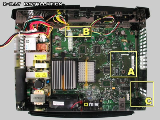

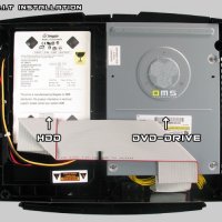
Remove the DVD-Drive and the HDD. You do not need to remove the XBox mainboard.
You need to get acces to areas "A", "B" and "C".
Step 3
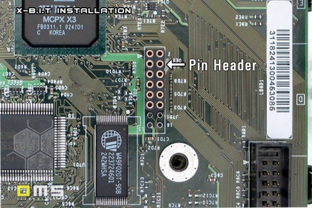

You need to solder a 12 pin header to the XBox LPC port like shown on the image above.
Step 4
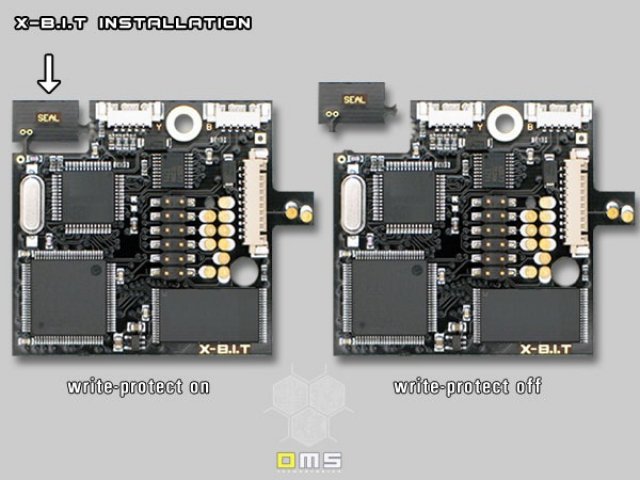

Grasp the seal with your thumb and your forefinger and break it away.
Step 5
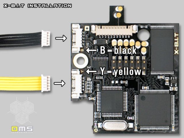

Connect the wires to the internal board as shown above and ensure that you don't mix up the wires. Connect the yellow wires to the socket marked with "Y"and connect the black wires to the socket marked with "B".
Step 5a
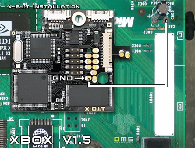

Attention: This is step is only necessary if you modify a v1.5 console. The GND connection got removed from the LPC Port. You need to solder a bridge as shown on the image above.
Step 6
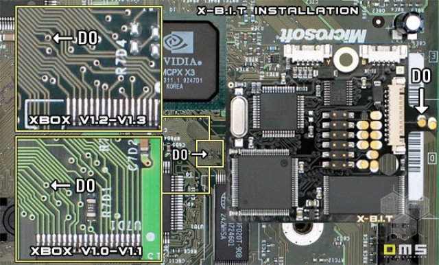

Specify the version of console you have and solder a wire from the "D0" via of the XBox the "D0" pad of the X-B.I.T internal board like shown on the image above. The wire should be at least 6cm long since you will need to turn the chip 180°.
Step 7
Attention:
Step 7 is an alternative installation for users that want to activate/deactivate the X-B.I.T Stealth-Mode
by pressing the XBox power button as described in the Link above. This step is not essential.
Click here if you want to use the XBox power button to activate/deactivate the X-B.I.T Stealth-Mode.
Attention: Soldering iron required!!!
If you do not wish to solder to your XBox continue with step 8. The X-B.I.T Stealth-Mode can also be activated/deactivated with the dip-switch on the X-B.I.T external board.
Step 8
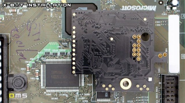

After soldering the "D0" bridge you can plug the pin header into the socket. Please insulate the pogo pins with non-conductive adhesive-tape to prevent any shorts.
Step 9
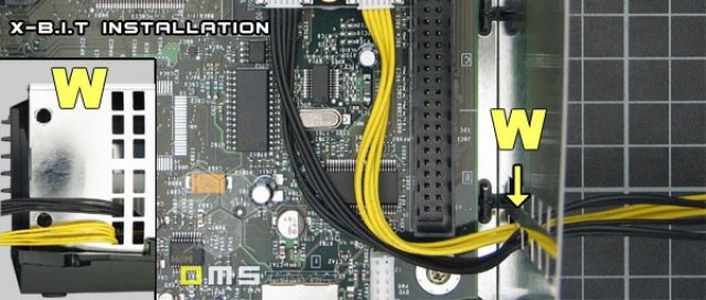

Route the wires carefully to the casing of the XBox and put them carefully through the cut-outs of the casing as shown above. The internal installation is now completed.
Step 10
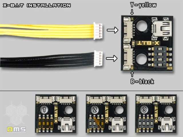

Connect the wires to the external board as shown above and ensure that you don't mix up the wires. Connect the yellow wires to the socket marked with "Y"and connect the black wires to the socket marked with "B". Remove the tape from the dip-switch.
Step 11
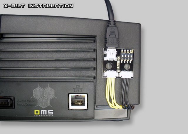

Route the wires carefully to the area of the XBox as shown above. Use adhesive-tape to fix the X-B.I.T external board on the back of the XBox. The physical installation is now completed.