Copy Link
Add to Bookmark
Report
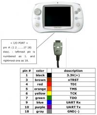
I/O PORT PIN DEFINE

pin   #name      description
1     3.0V(+)    power +3.0V
2     RESET      Machine reset
3     nTRST      nTRST (TAP Controller Reset)resets the TAP controller at start.
4     TDI        TDI(TAP Controller Data Input)is the serial input fot test instructions and data.
5     TMS        TMS(TAP Controller Mode Select)controls the sequence of the TAP controller’s states.
6     TCK        TCK(TAP Controller Clock)provides the clock input for the JTAG logic.   7 TDO TDO(TAP Controller Data Output)is the serial output for test instructions and data.
8     AIN0       Analog to Digital Input 0 Port.
9     UART Rx    UART receives data input.
10    UART Tx    UART transmits data output.
11    IICSCL     IIC-bus clock
12    IICSDA     IIC-bus data
13    nRTS       UART request to send output signal
14    nCTS       UART clear to send input signal
15    Rx1        UART receives data input port1.
16    Tx1        UART transmits data output port1.
17    N.C.       Non-connection
18    GND(-)     power GND(-)